Good afternoon!
This Afternoon's Update:
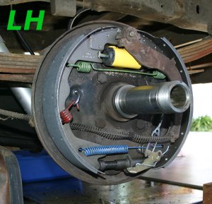
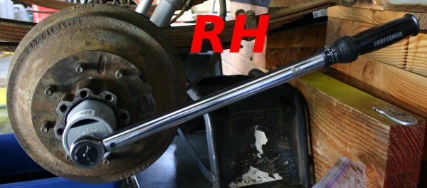
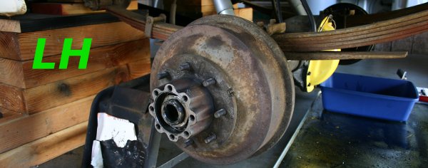
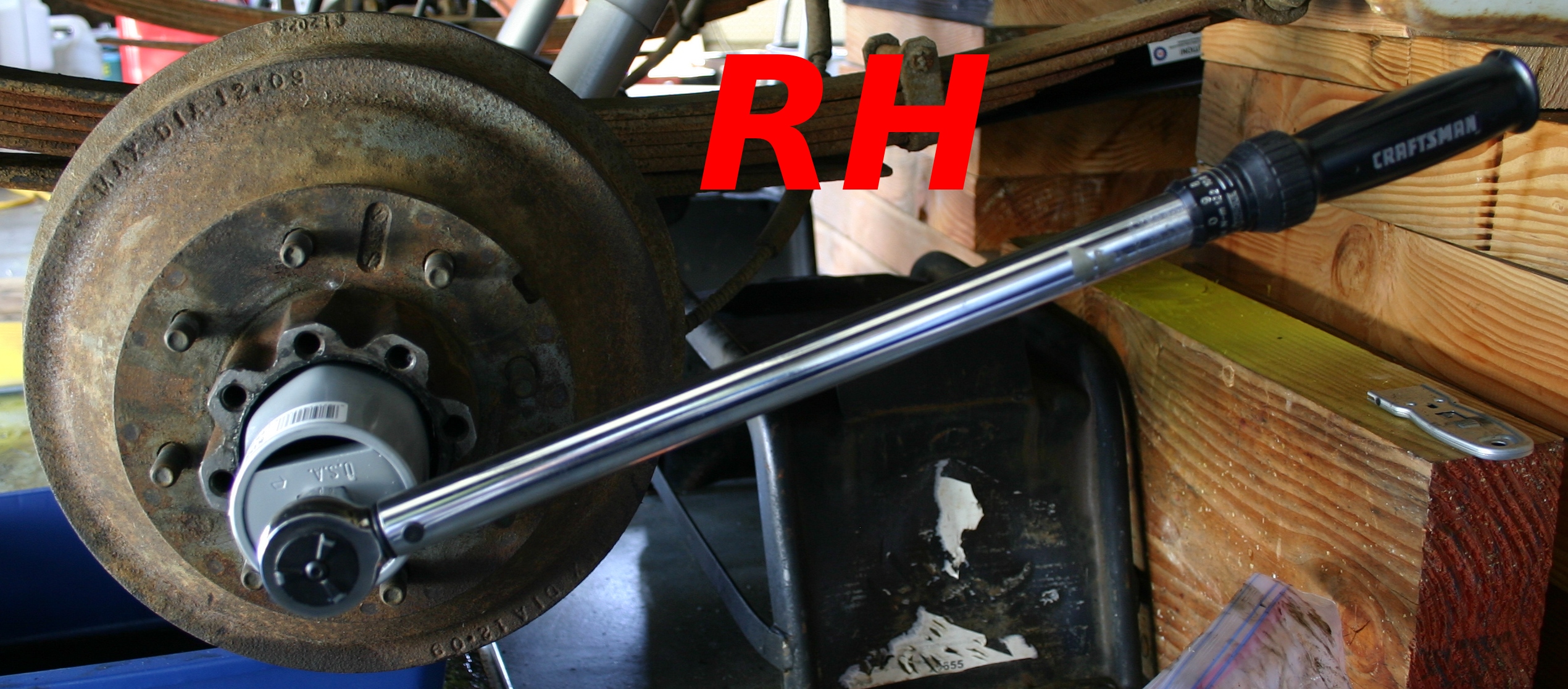
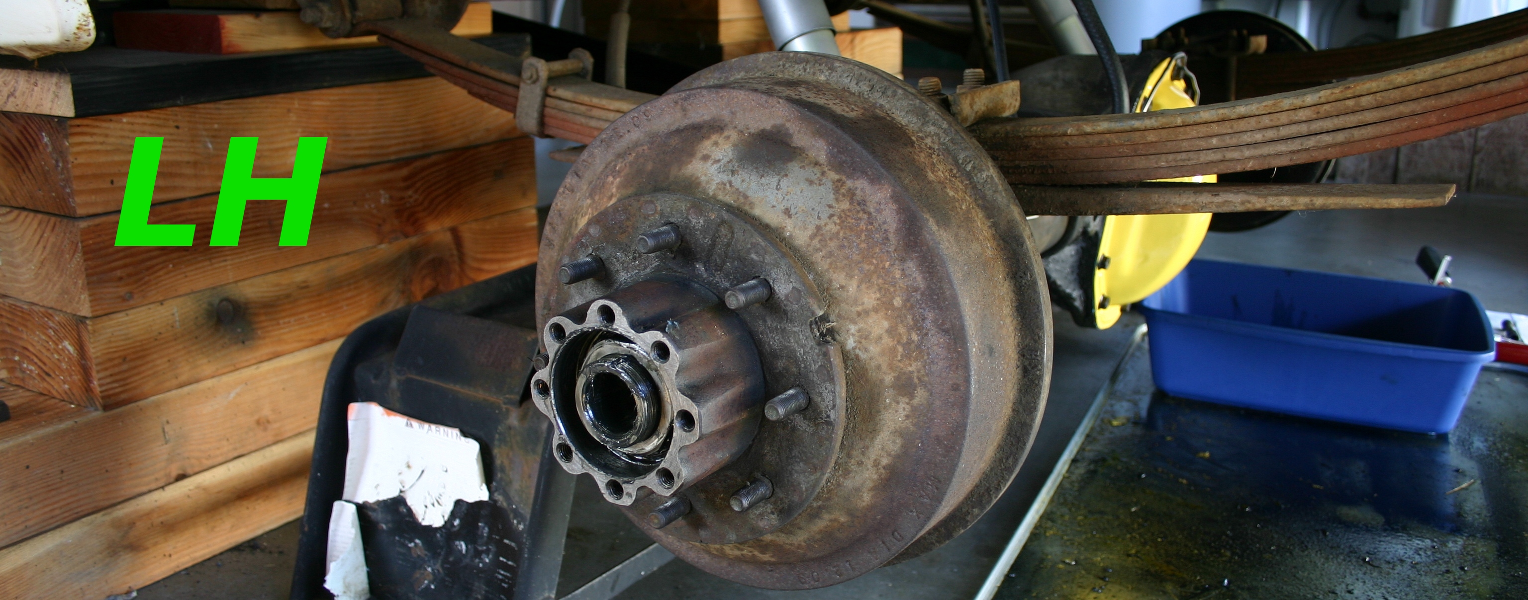
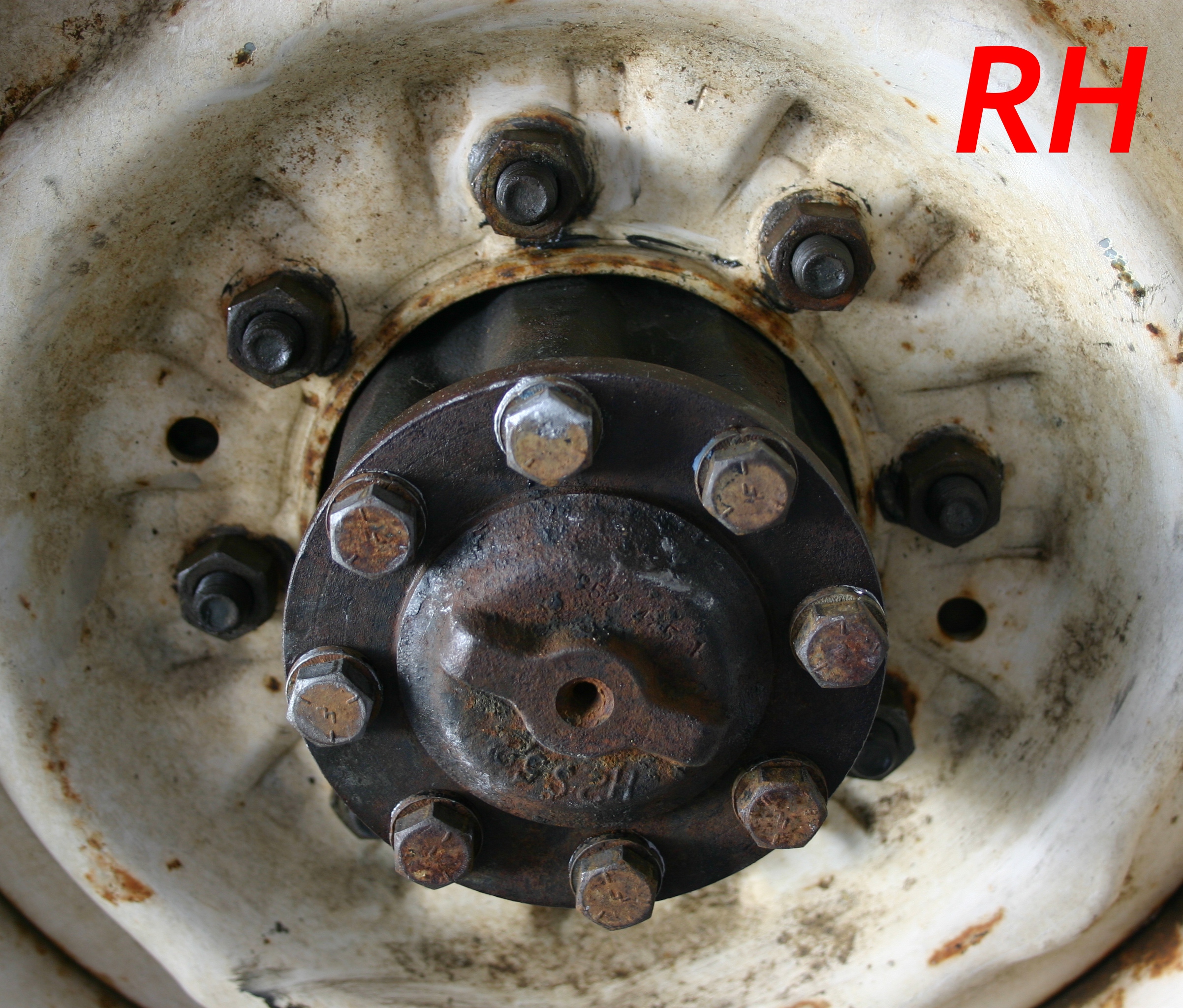
Yesterday I dissected both parking brake lever assemblies to make sure they were put together in the same order as shown in the various diagrams. As y'all may have gathered by now, the photos that aren't marked feature LH-side parts, while the photos showing RH-side parts tend to be marked, "RH." (Just to keep you guessing, a few of the LH-side photos
are marked "LH.")
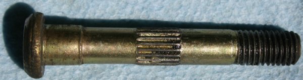
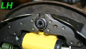
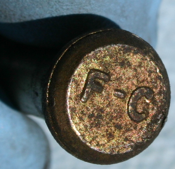
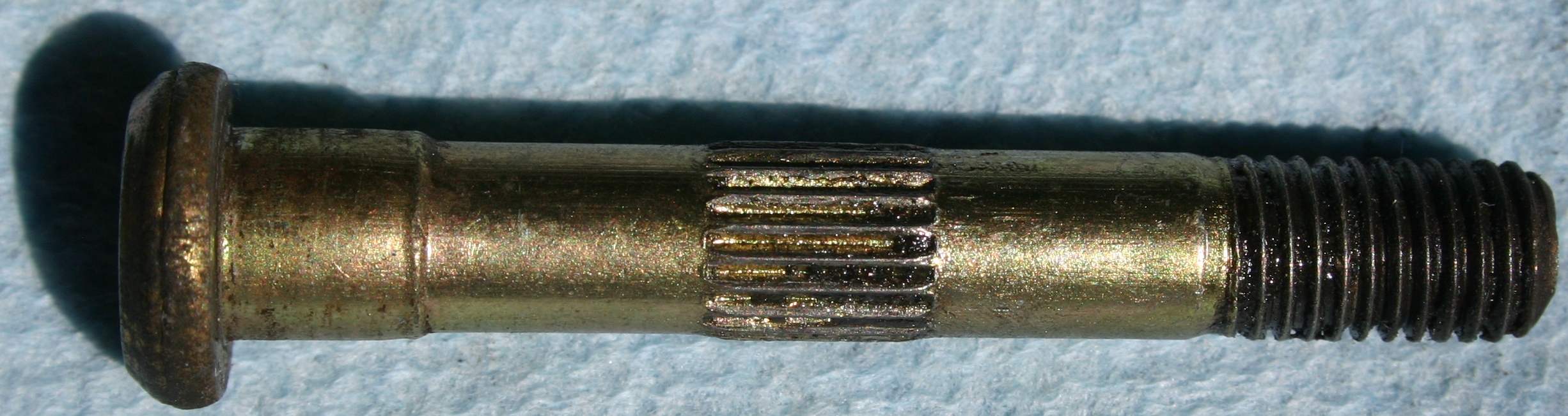
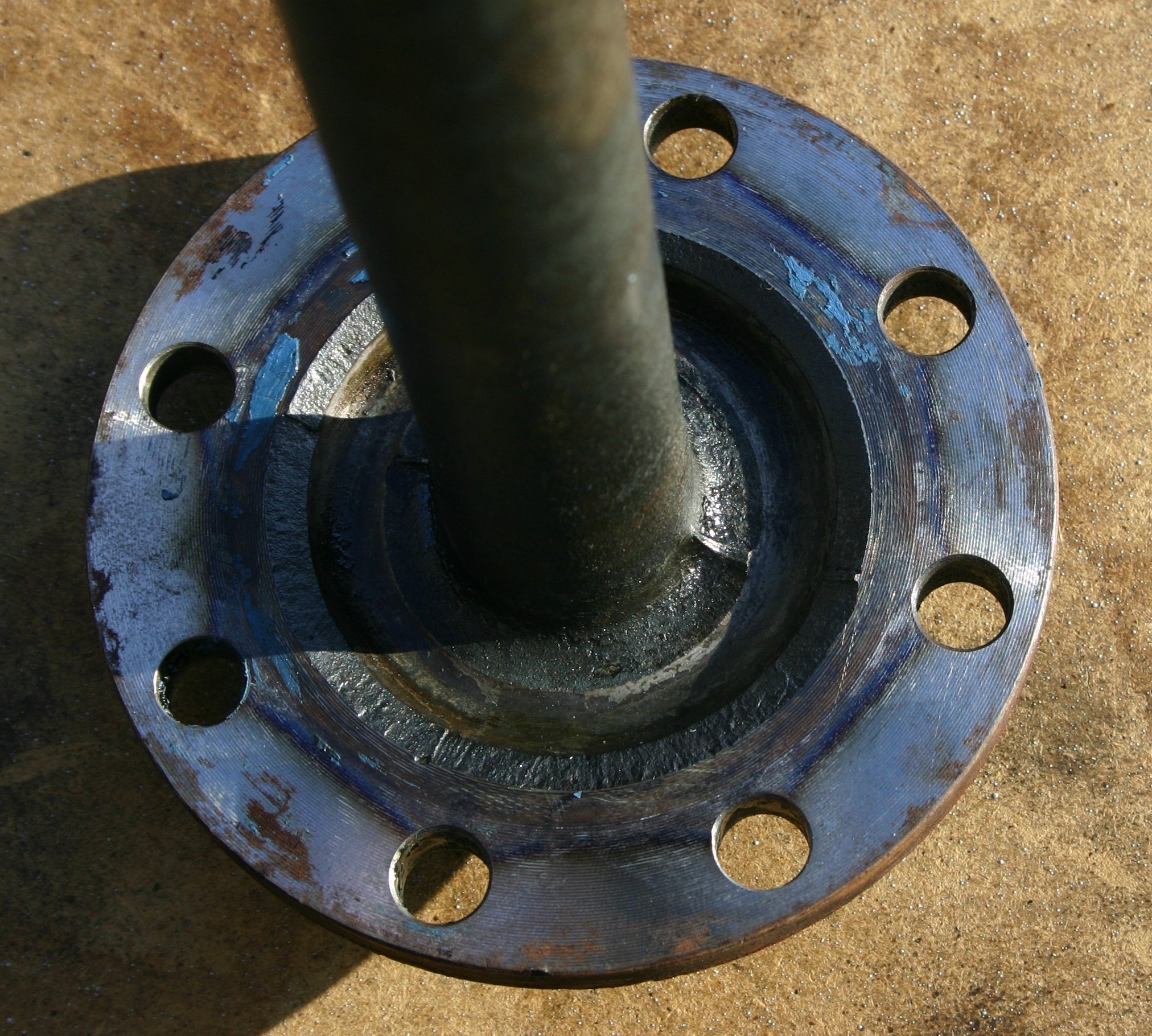
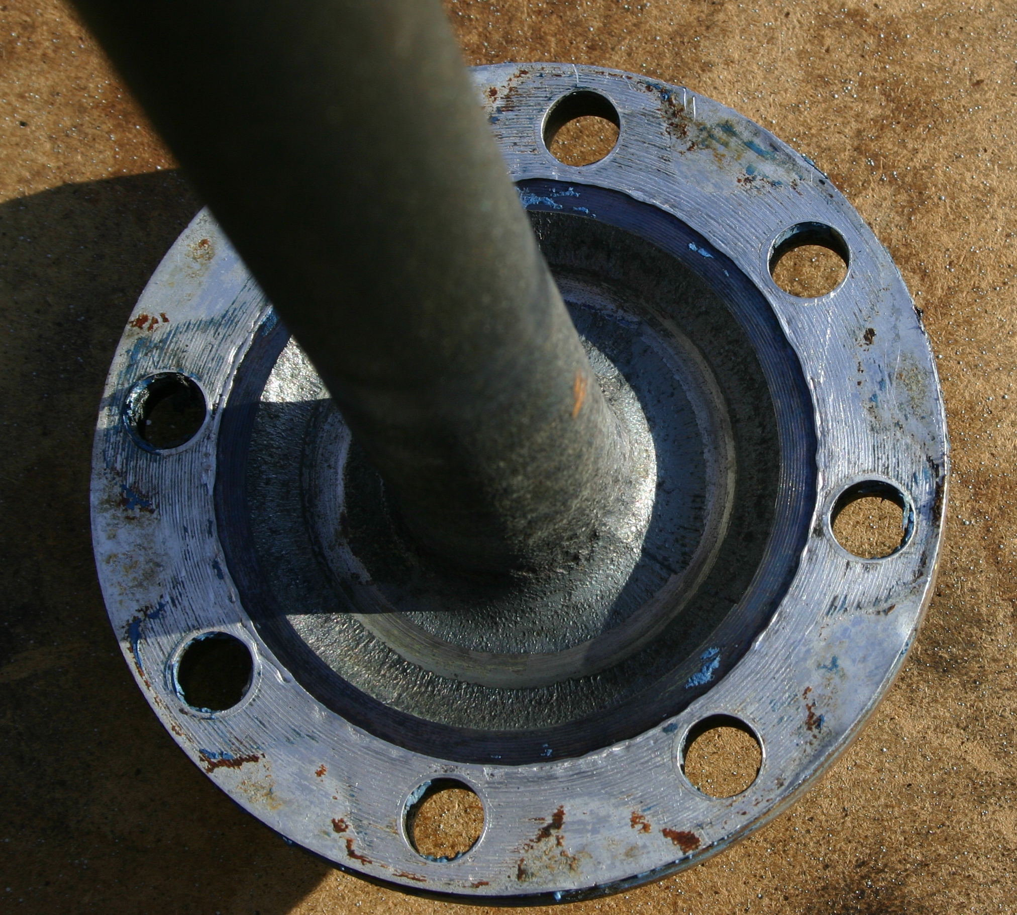
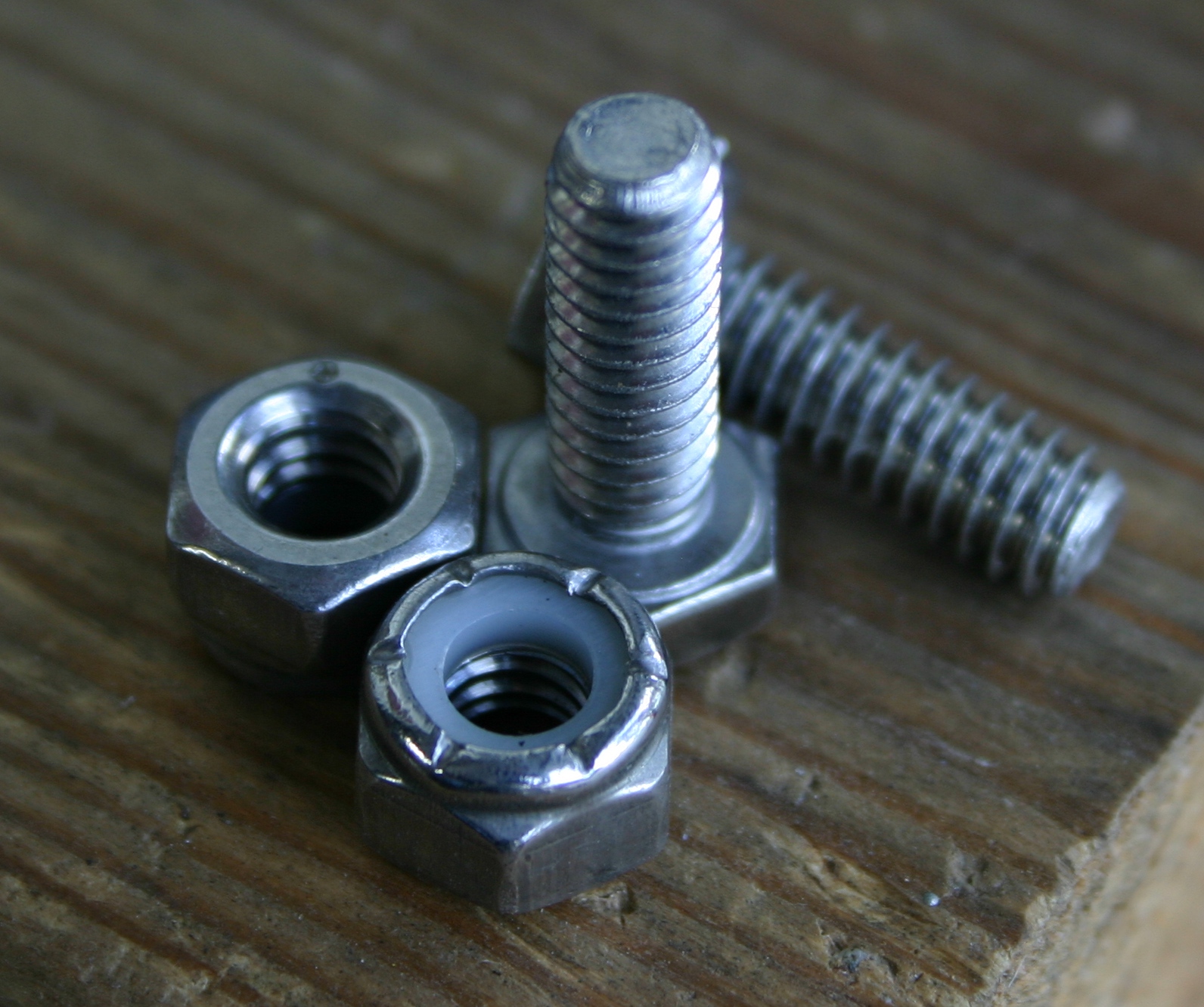
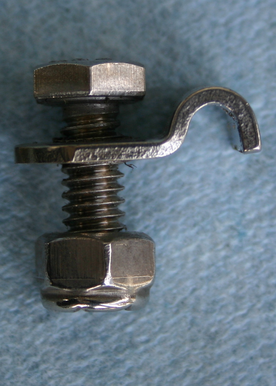
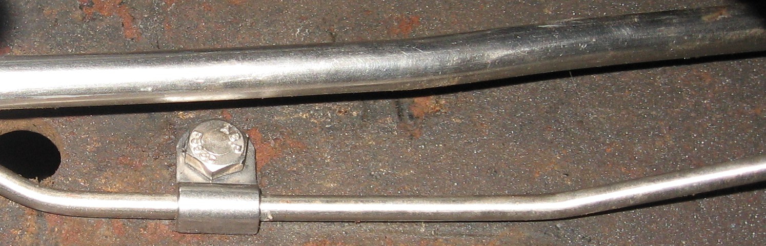
Here's the LH parking brake assembly bolt. All of the diagrams I've seen so far show a hex head on this bolt, while you can see that mine has a round head. Perhaps they made it this way to keep folks from over-tightening the nut that holds it to the backing plate?

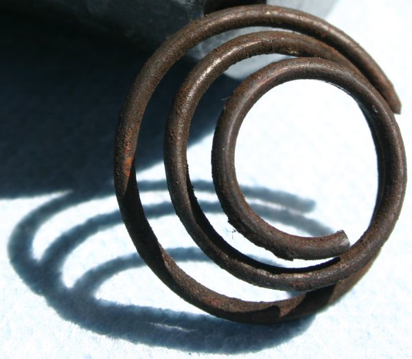
Here's the LH-side 2A601 spring.
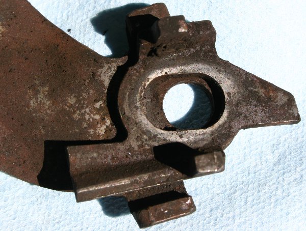
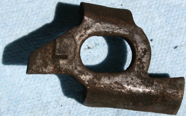
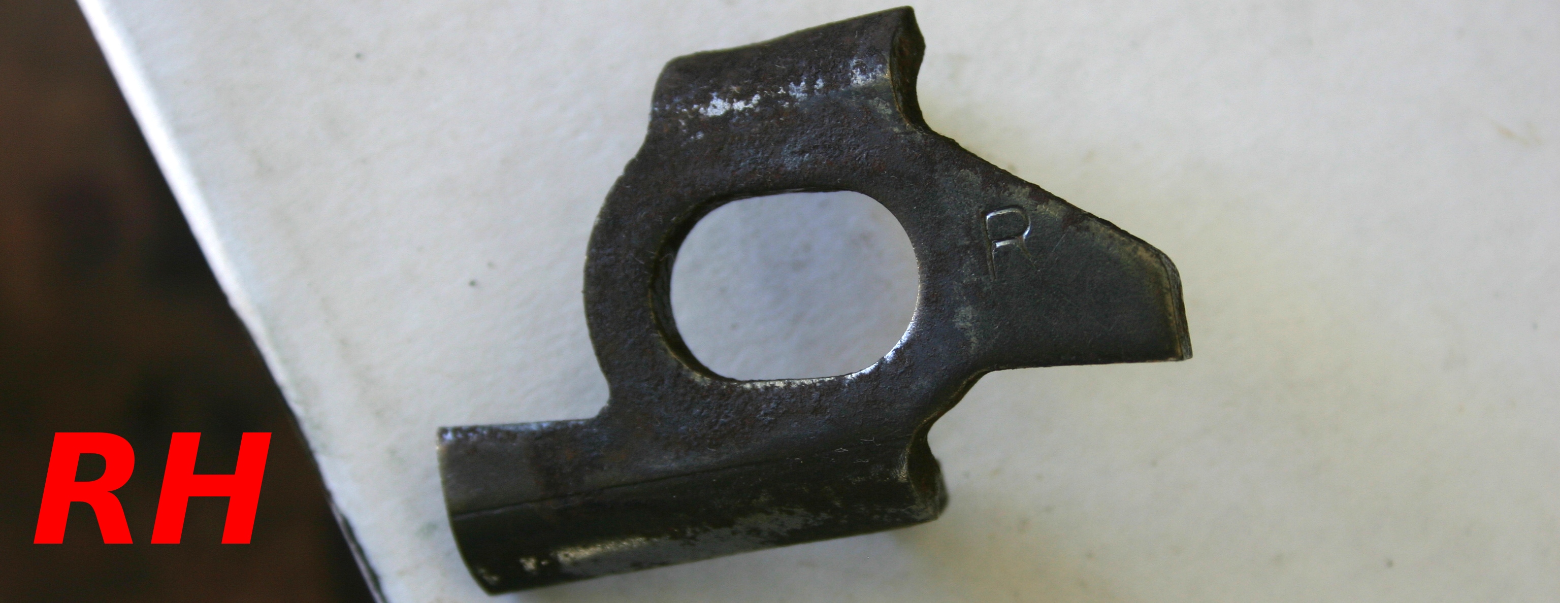
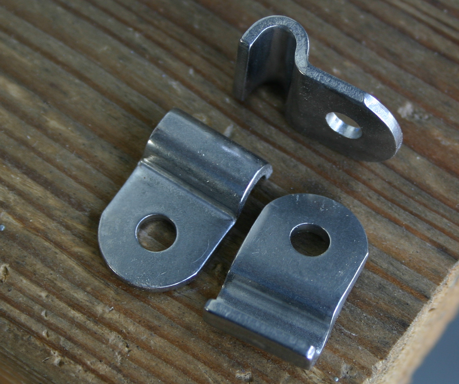
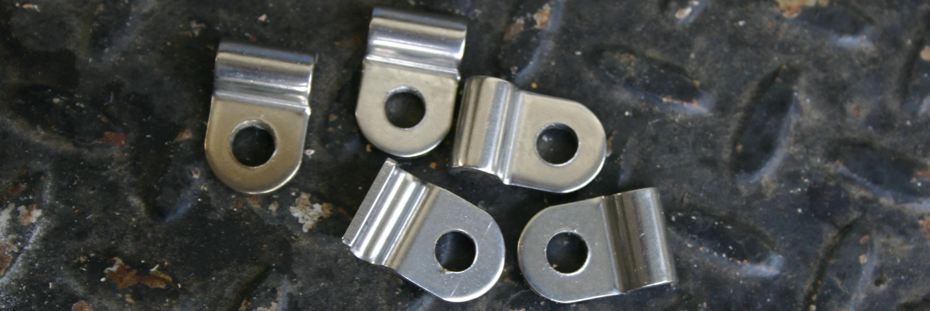
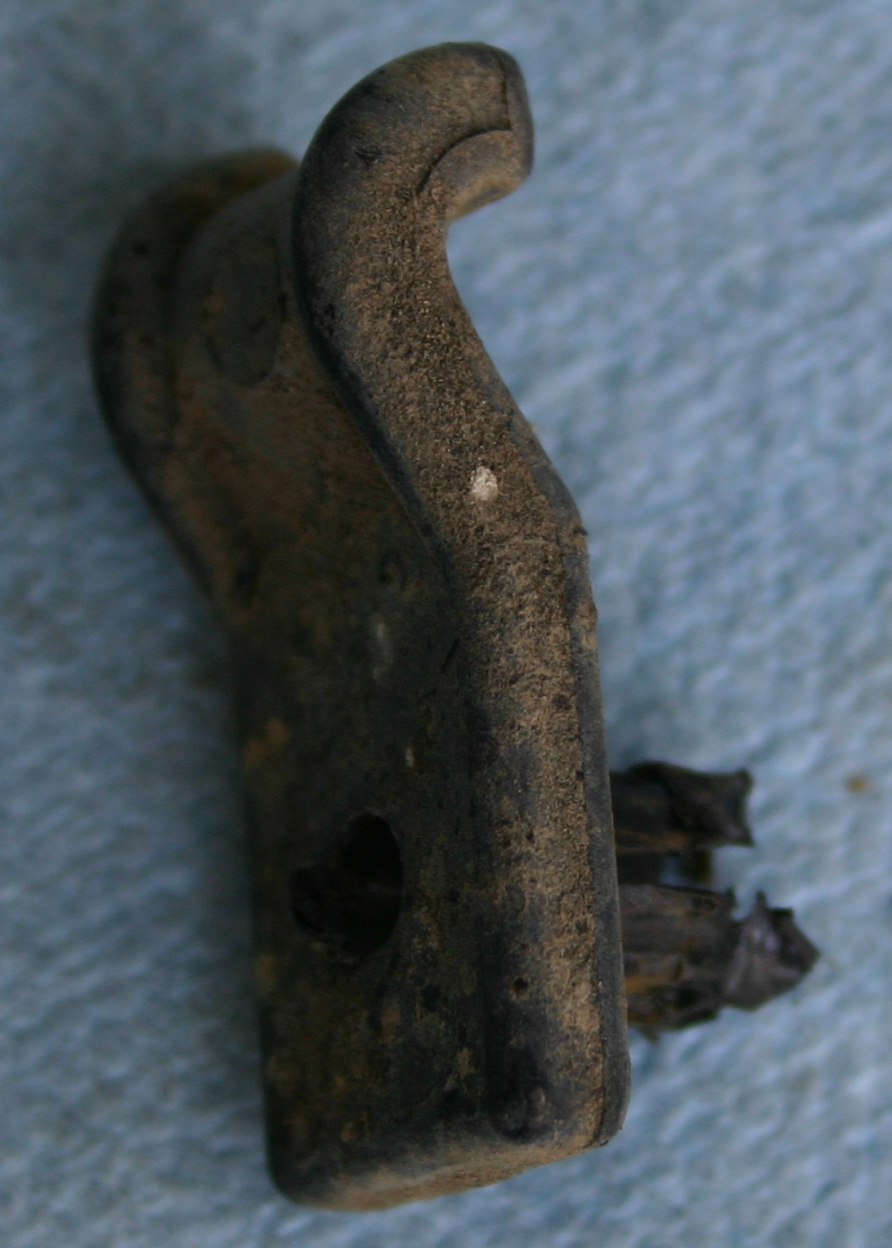
Here's the LH-side 2A142 "chicken head bracket" resting on the parking brake lever, and 2A142 all by itself below. Note that "L" is stamped on; "R" appears on the RH side part. These photos aren't illustrative of anything strategic yet I thought I'd include them on general principles.
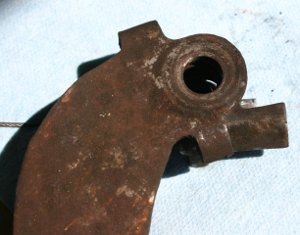
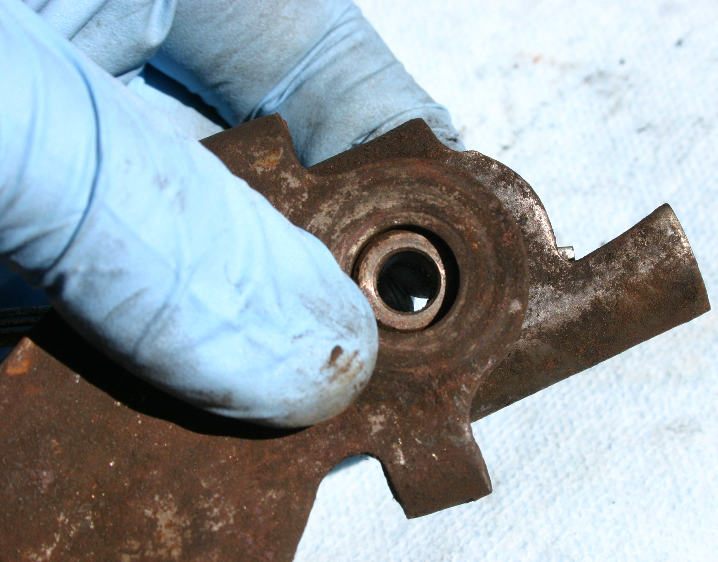
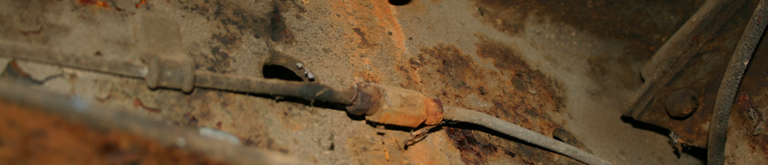
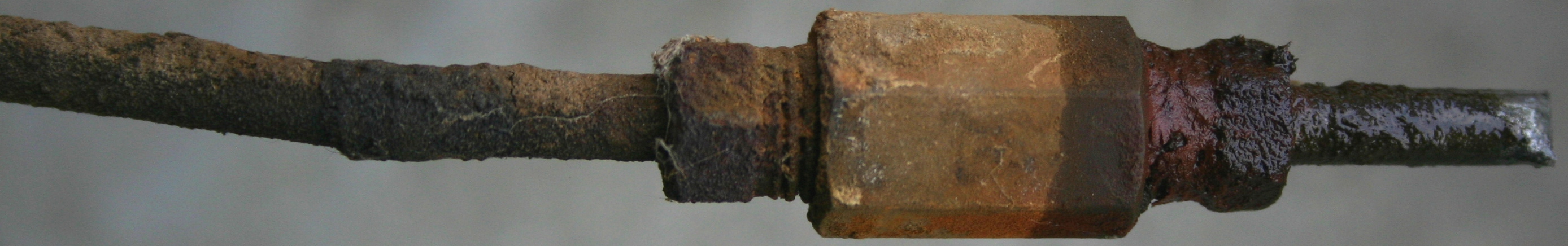
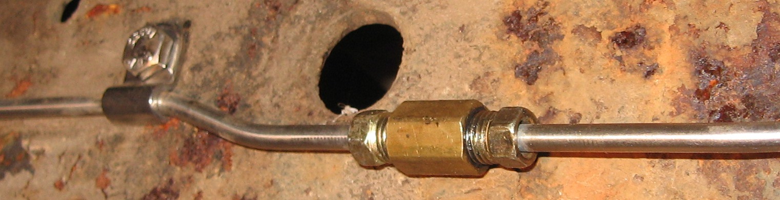
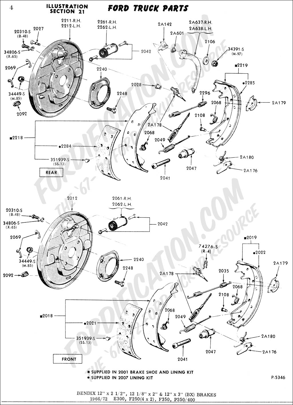
Here's the cable anchor fitting (2A178) with the odd spacer, "2028," that fits inside of it. It's a mystery that this odd "2028" spacer doesn't appear in either of the 1970 or 1972 Ford Truck Shop Manuals (as far as I can see). Yet it does appear in
this diagram referenced by Fordman.
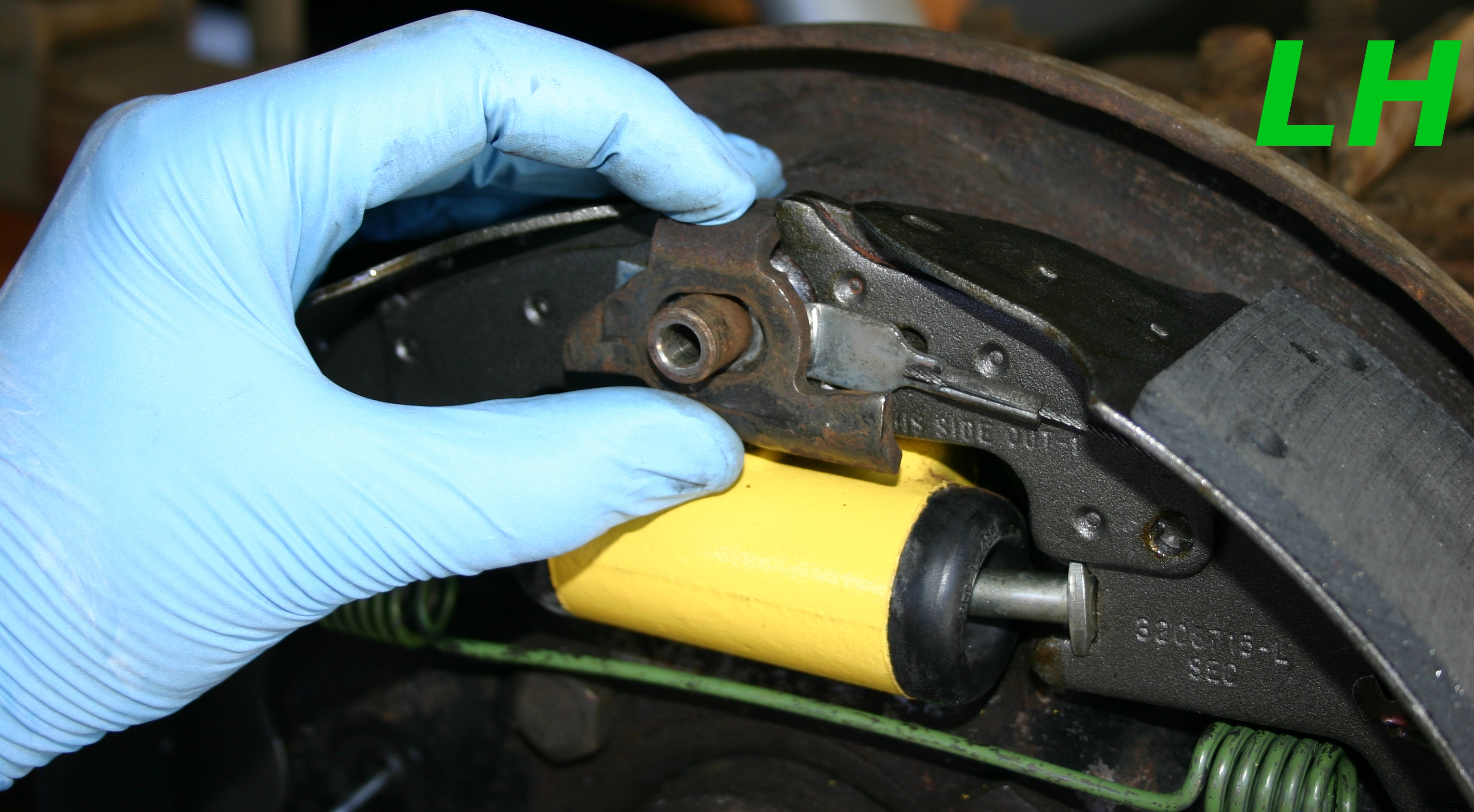
Here's more or less how the "chicken head bracket," 2A142, sits on top of the cable anchor fitting (2A178) and the 2028 spacer (left). On the right, I've added in 2A601. I'll show how these parts fit together in better context with additional photos later in this post (of the actual build-up), yet perhaps these individual photos will be helpful as well.
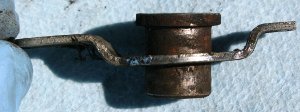
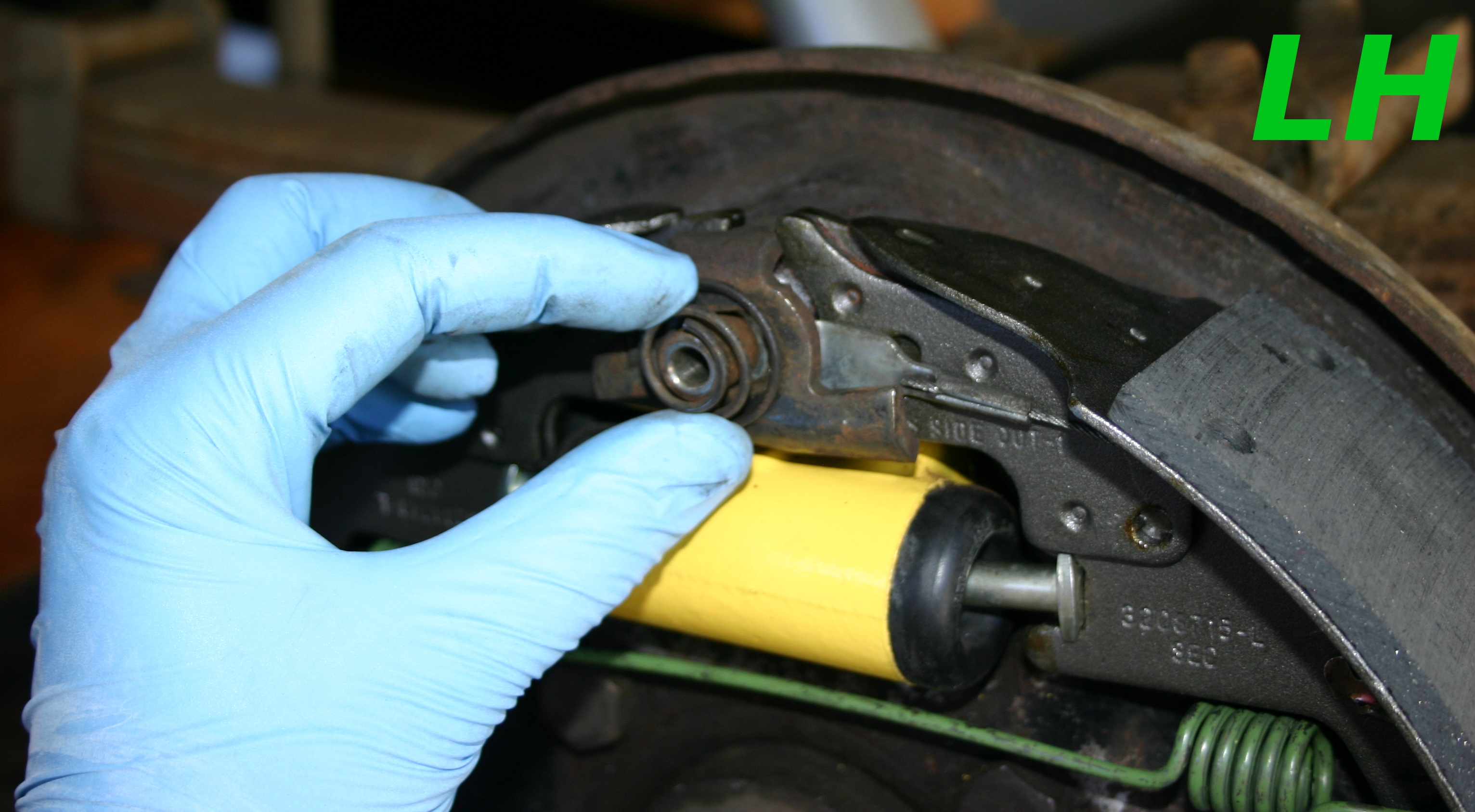
Here's how the parking brake lever stacks on top of the parts shown so far (left). You can see that when it's pressed down, it compresses the 2A601 spring and 2028, the odd spacer, sticks all the way through (right). Below these two photos is a side view of the sandwich, including the lettuce, pickles, and tomatoes.
Here's the large washer that sits under the head of the parking brake assembly bolt. It was bent on both the LH and RH sides, which suggests that the placement of the 2A601 spring was probably incorrect before! I used a large hammer and a flat metal place to smash it out flat again.
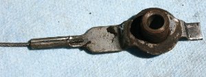
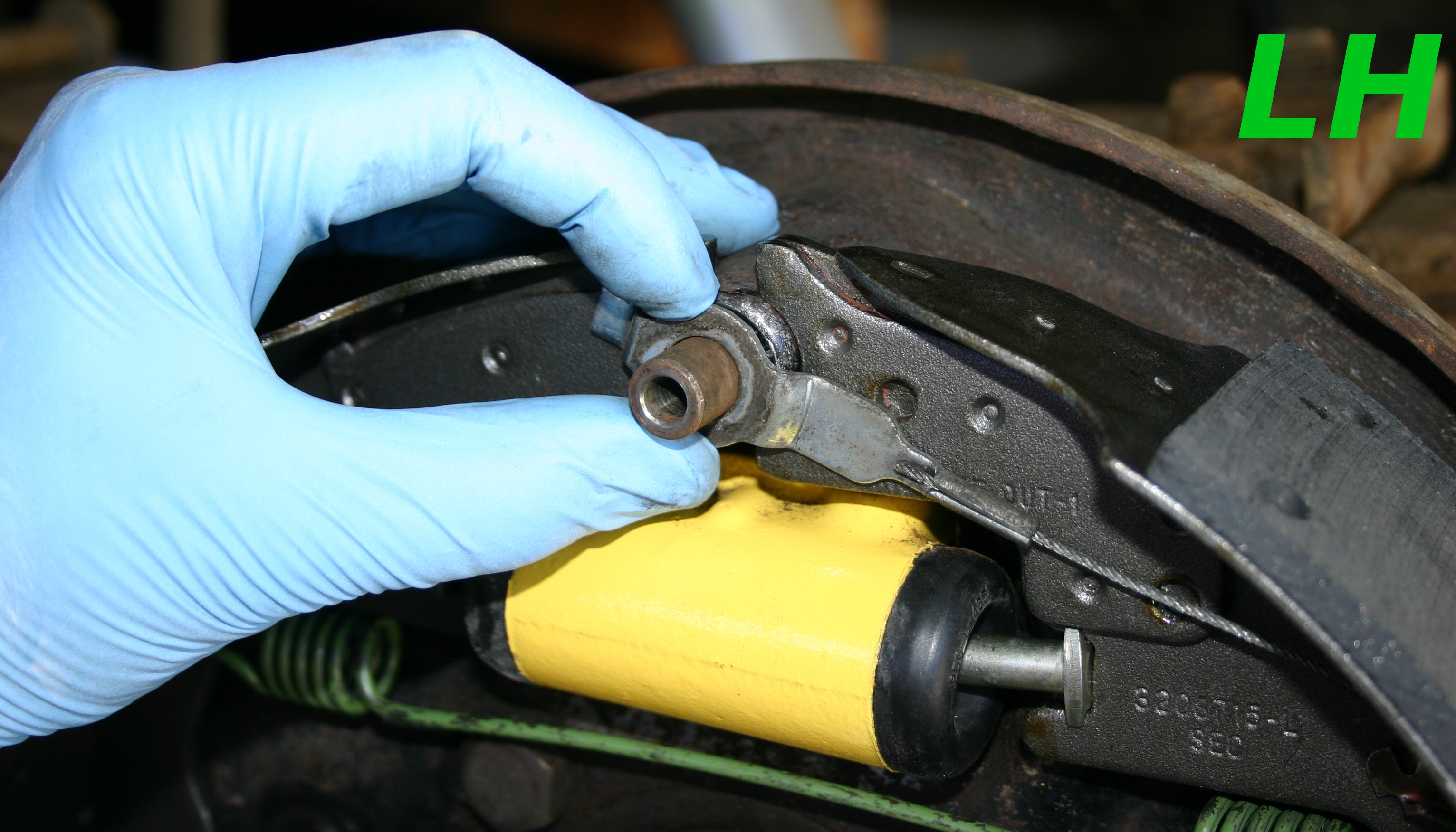
Here's the LH-side adjuster assembly after I'd pushed it in to place. It seems to be able to "float" around before it's put under tension by the cable that terminates at it, as suggested by Eric! Below this photo, you can see that when the cable's attached, it's kept in perfect order.


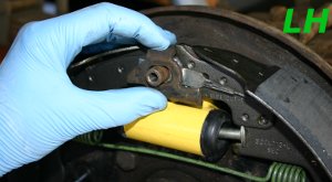
Returning to the parking brake lever, these photos illustrate the (I think) proper build-up of its constituents. You'll see this illustrated again for the RH side later in this post.
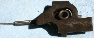
In the beginning nothing's there (left). The first step's to slide the odd spacer (2028) in to the cable anchor fitting (2A178) as shown, and hold it up nearby the top of the backing plate (right). I left the bottom part (with the spring) loose at this phase.

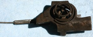
Next the "chicken head bracket," 2A142, goes over the odd 2028 spacer as shown (left). Note that the stamped in letter indicating its side (L or R) faces outwards, and the bracket's "beak" faces the front of the truck. With that in place, I set the 2A601 spring over the 2A142 bracket, centered on the odd 2028 spacer (right).

With the spring in place, I set the larger washer over its center, and carefully taped the parking brake assembly bolt through the center of everything. During this tapping process, you'll observe all the parts settle in to place naturally, or they'll bind up. I had to fiddle around with it to get the parts to go together harmoniously.
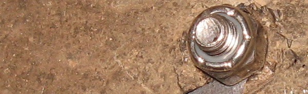
With the parking brake assembly bolt tapped through, I replaced the tiny locknut on the back of the backing plate that secures it, and torqued it to about 10 ft/lbs. I used a torque wrench for that; it wasn't a guess!

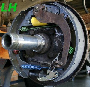
These two photos show the LH side complete and ready for the initial brake drum fitting process.
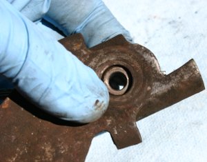
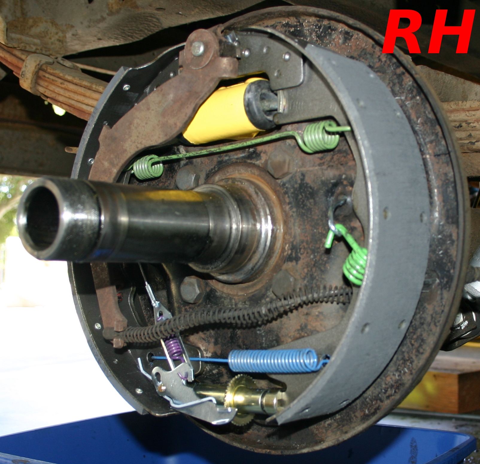
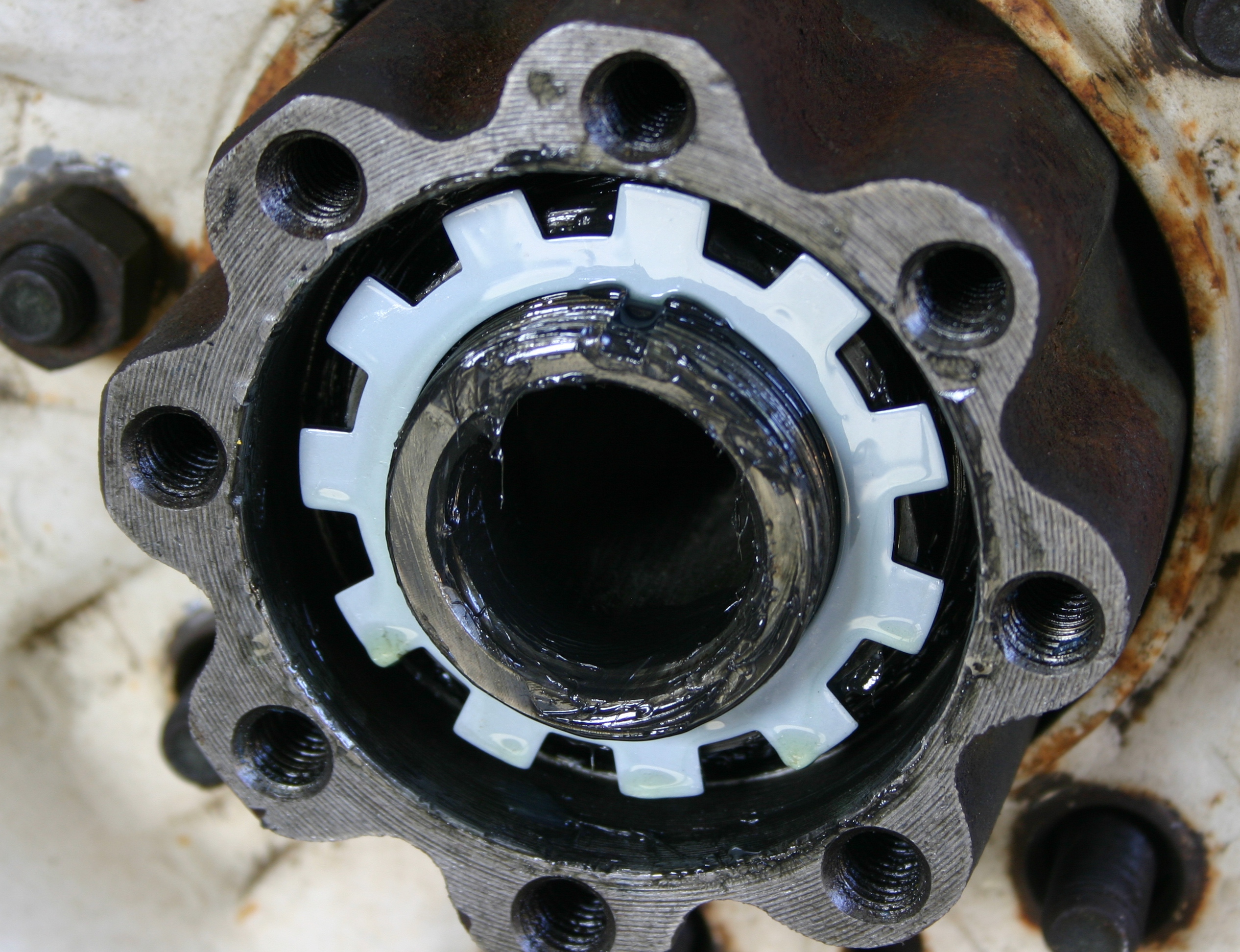
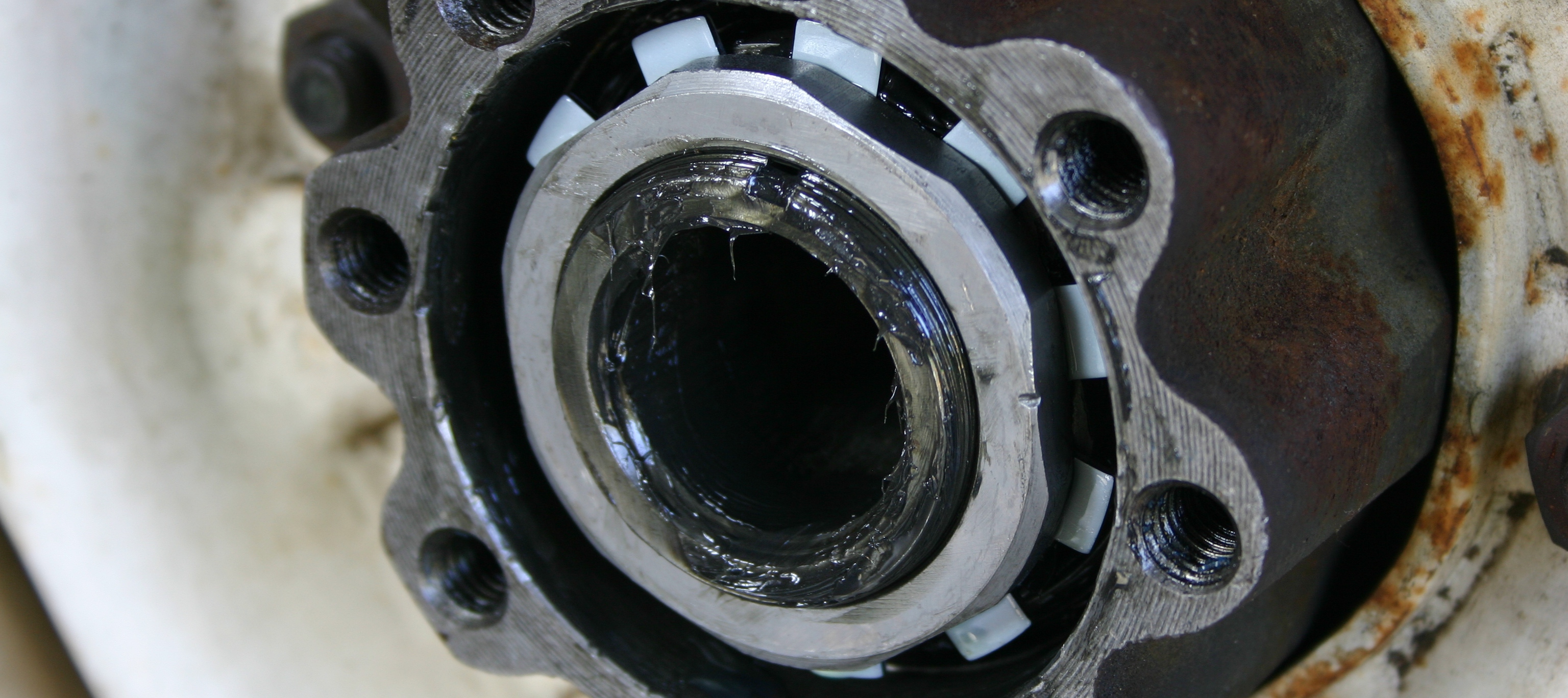
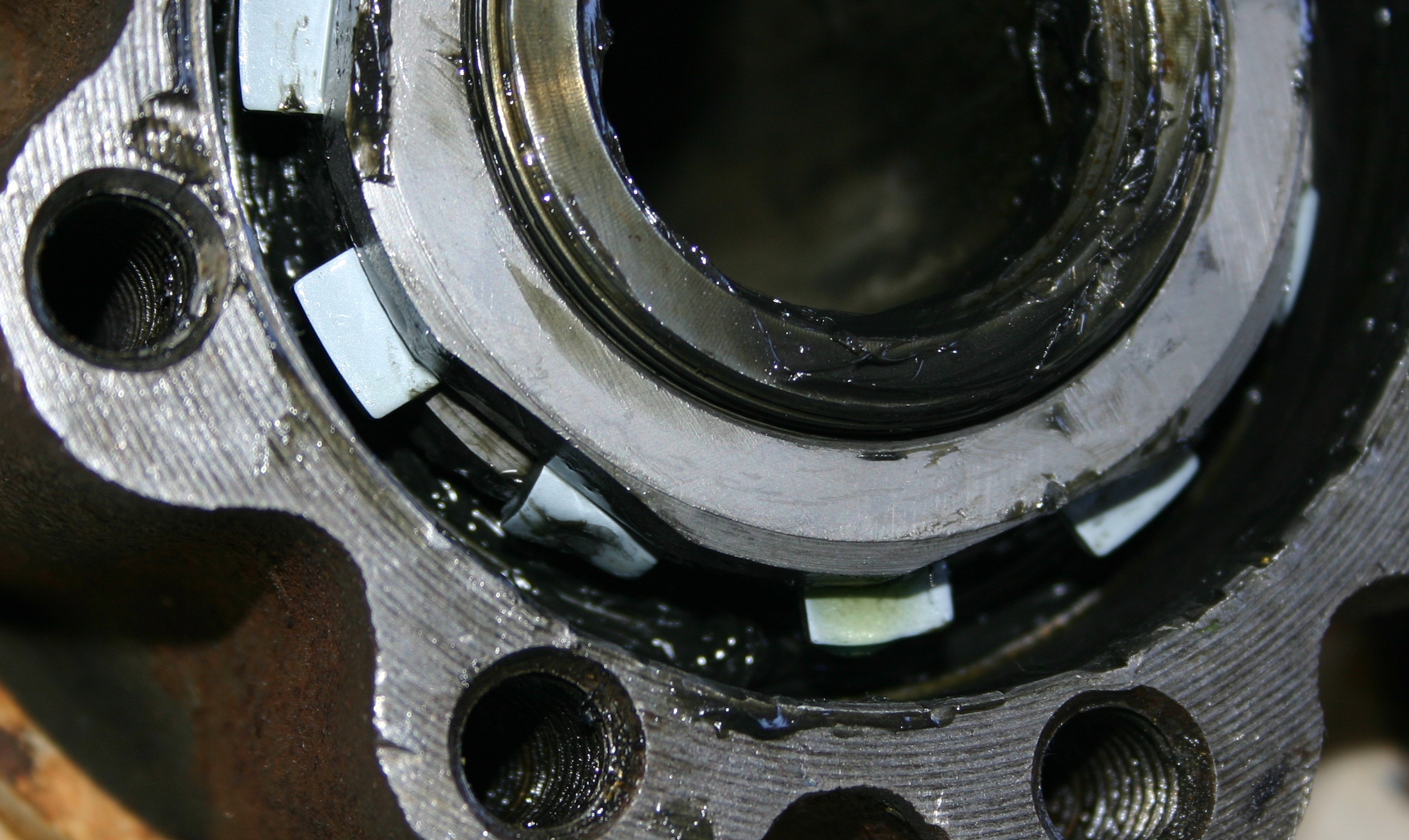
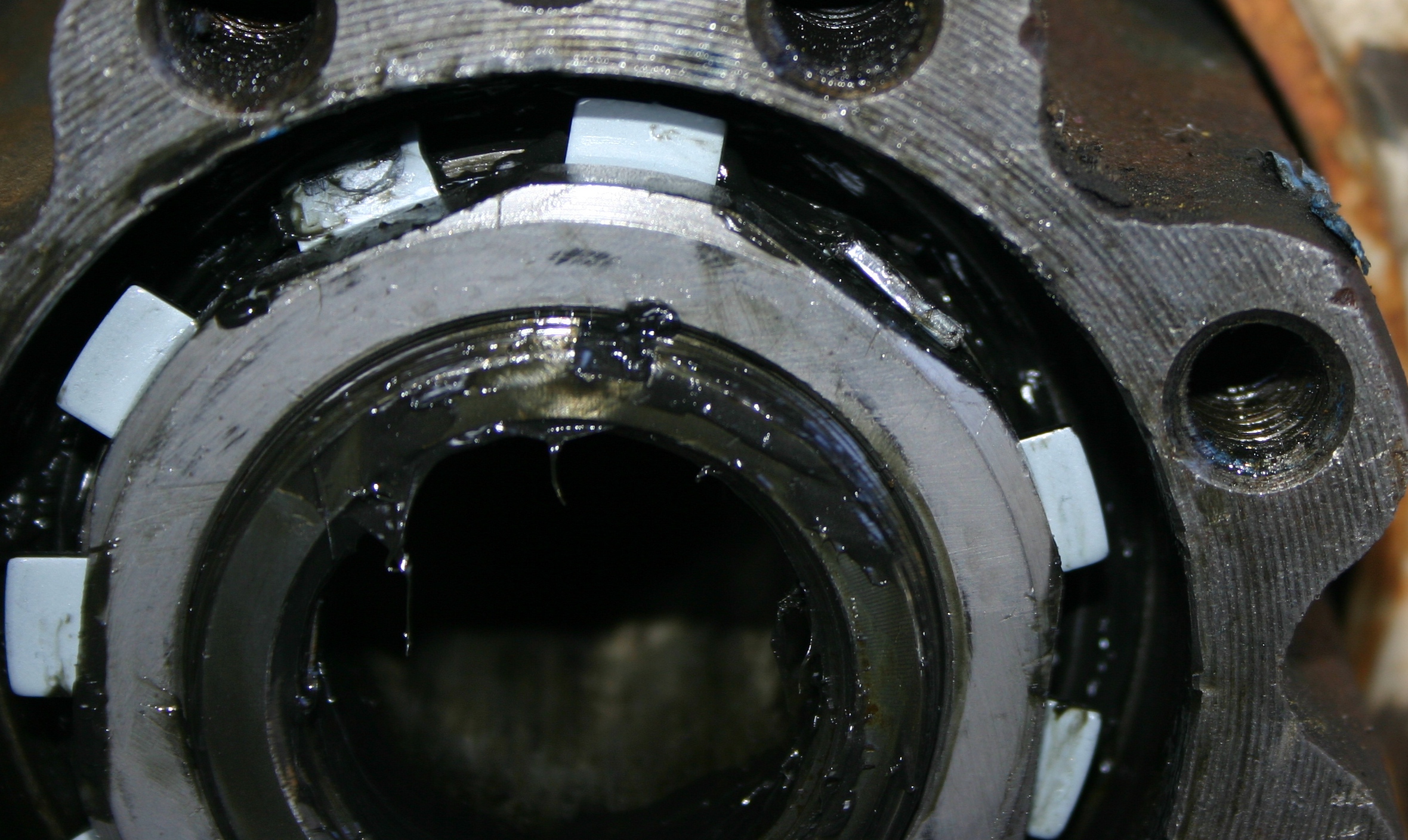
Next I dissected the RH parking brake lever assembly. This first photo shows how it was put together previously. As stated in my previous post, I believe the 2A601 spring was installed incorrectly.
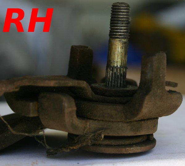
I found that because of the 2A601 spring being
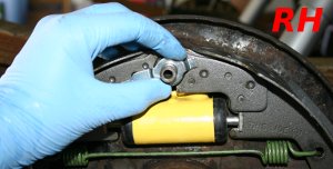
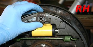
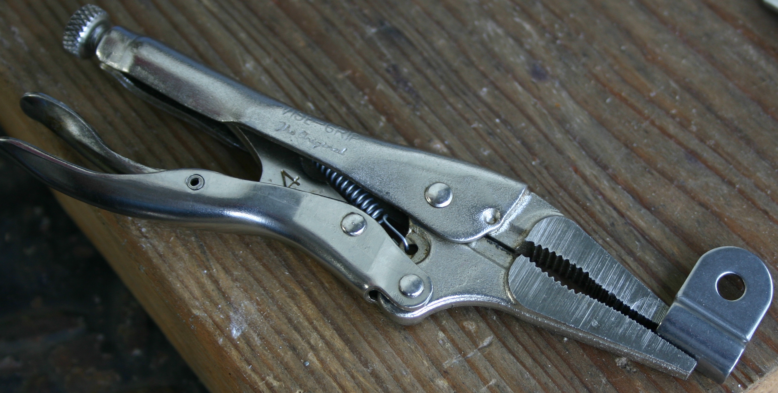
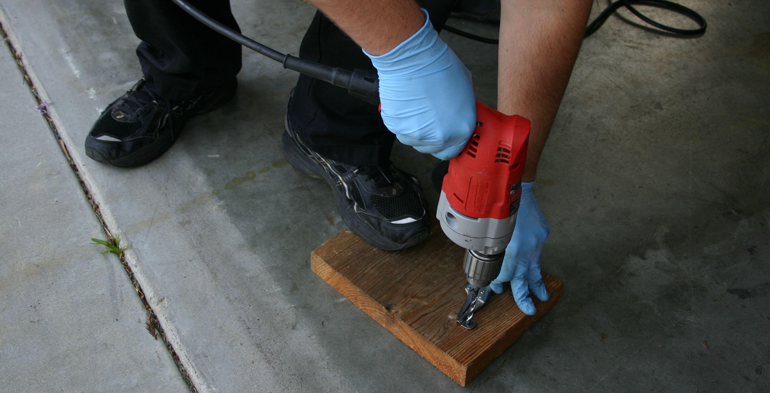
springy, the only way to take this assembly apart was to hold it still, and smack the parking brake assembly bolt right on its end! That worked wonders for the LH side. The RH side was more stubborn; here I'm failing at that technique.
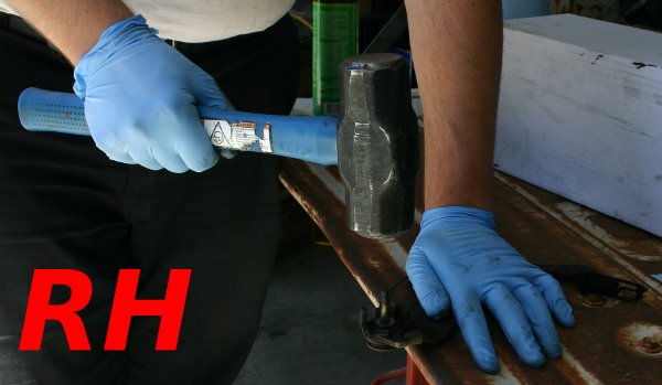
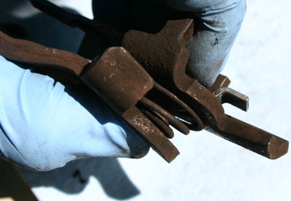
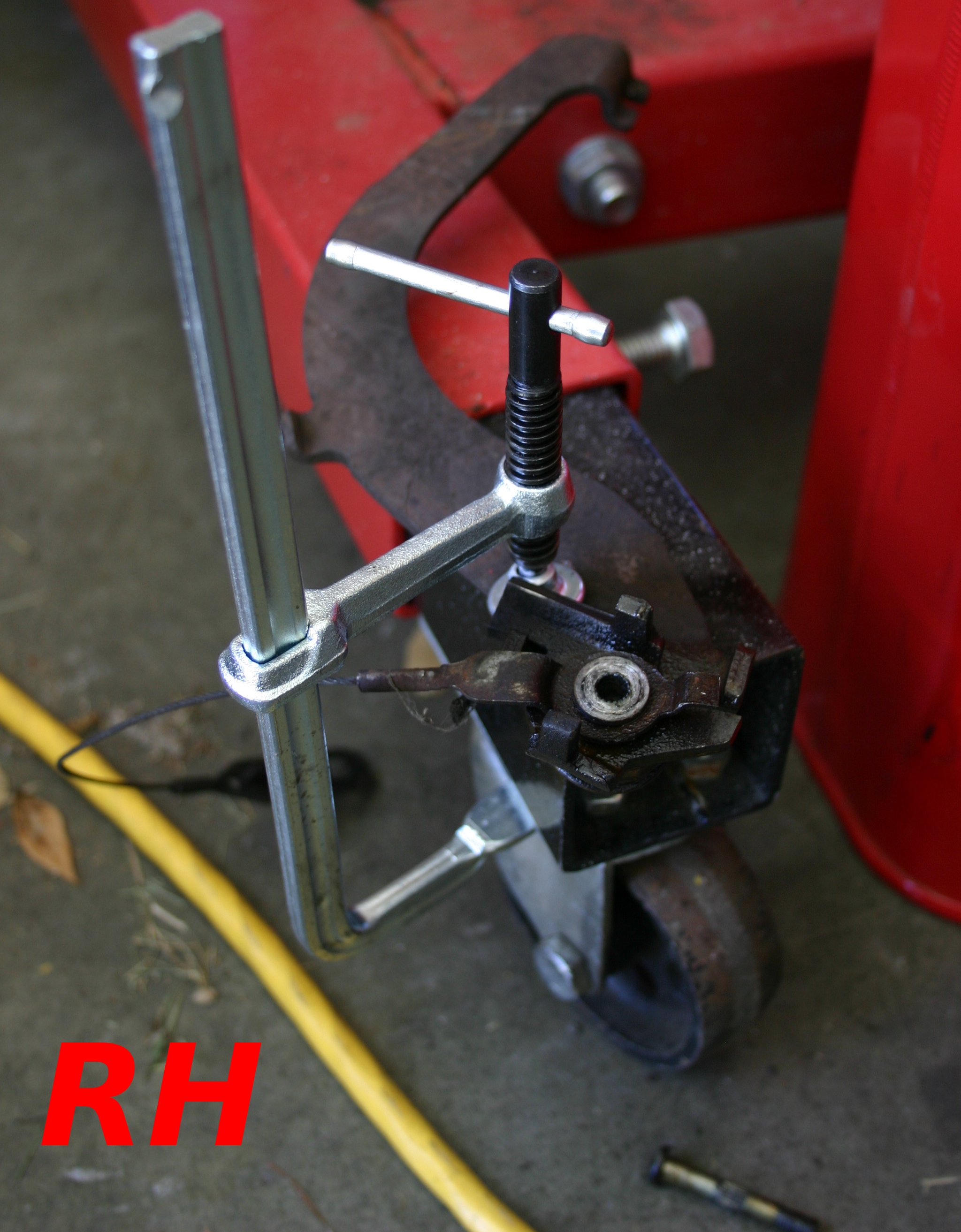
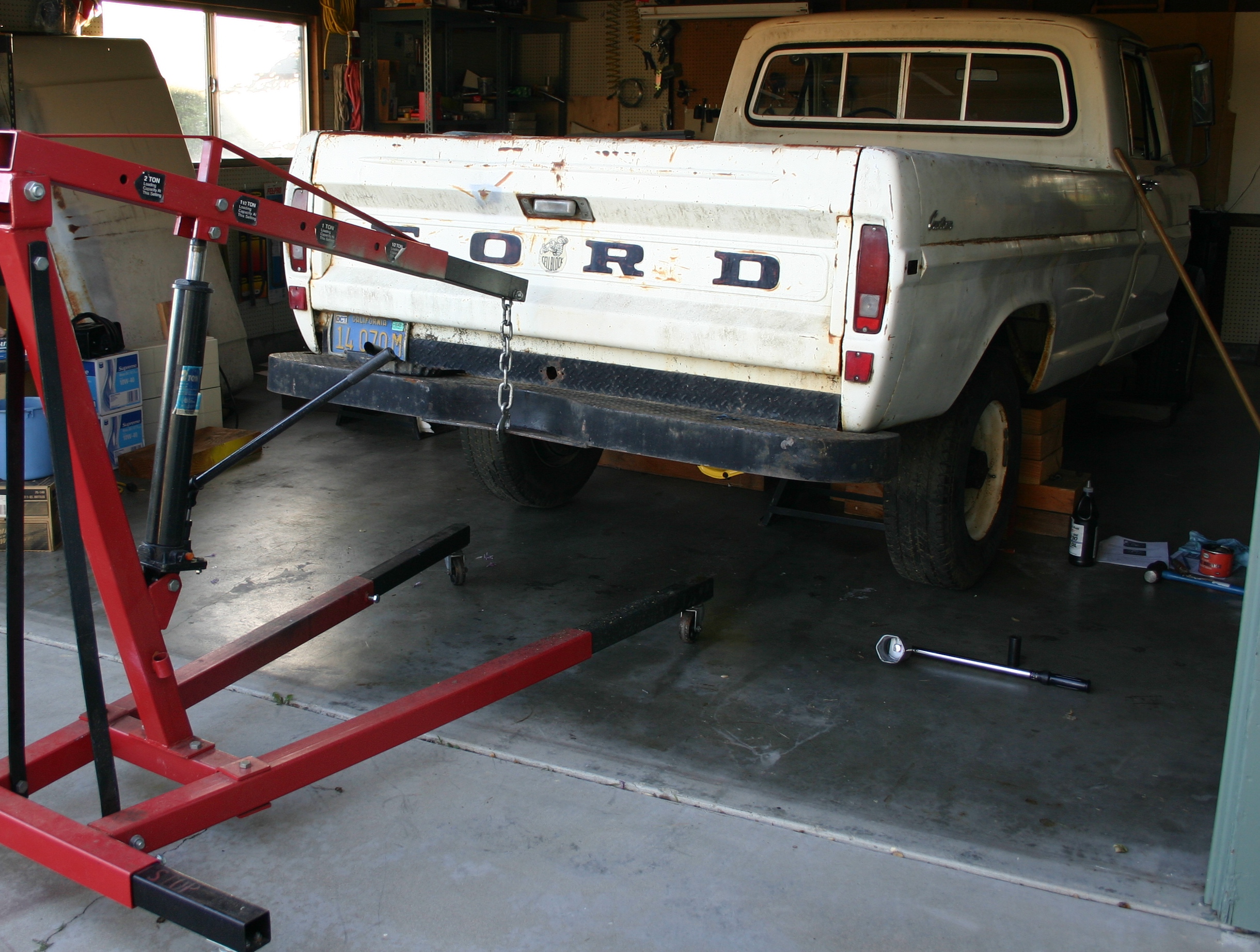
Since I don't own a vice, I came up with this funny makeshift setup to hold the lever still. The bolt responded to a couple of sharp smacks on its face this time! You can see it resting on the ground.

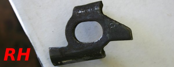
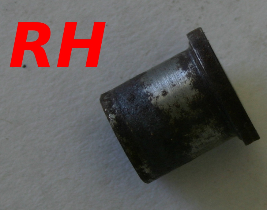
With the RH parking brake lever assembly busted apart, I took a few photos of the individual parts therein. Here's 2A142, the "chicken head bracket."
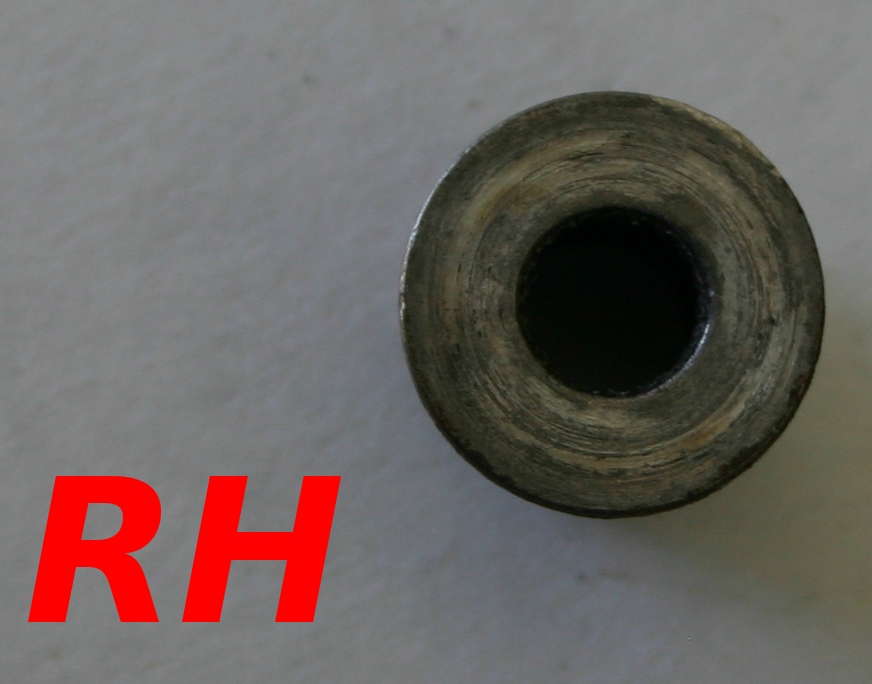
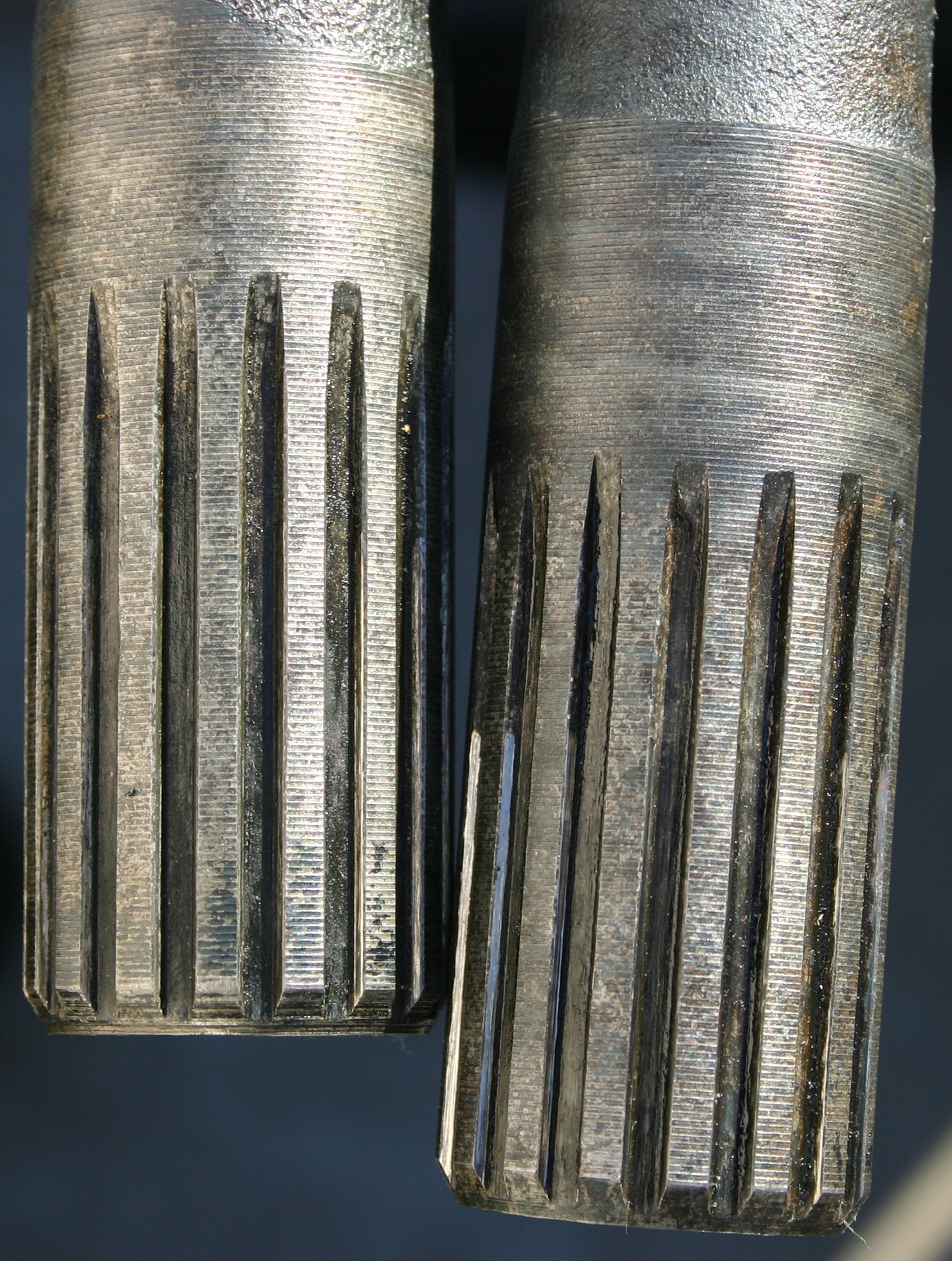
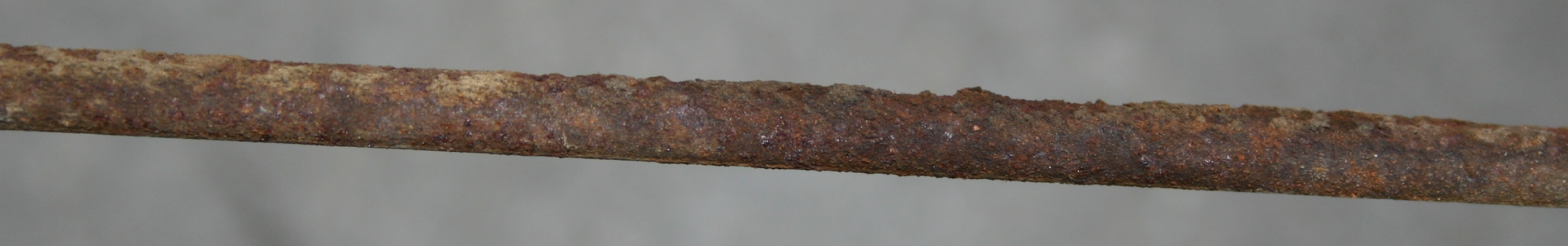
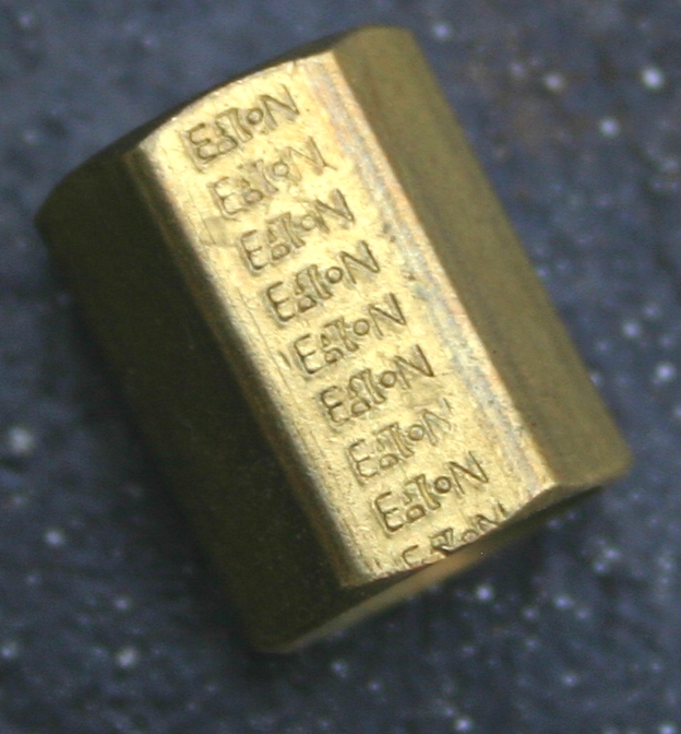
Here's 2028, the odd spacer. Note that this spacer actually has a spline in its center that mates to the spline on the parking brake assembly bolt.
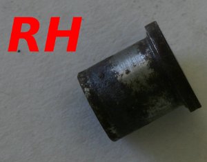

The 2A601 spring.

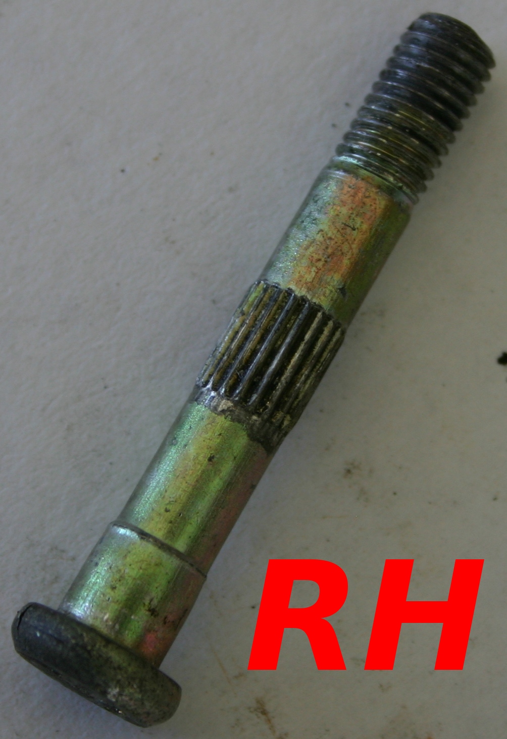
The parking brake assembly bolt--you can see the spline on its shaft.

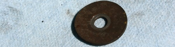
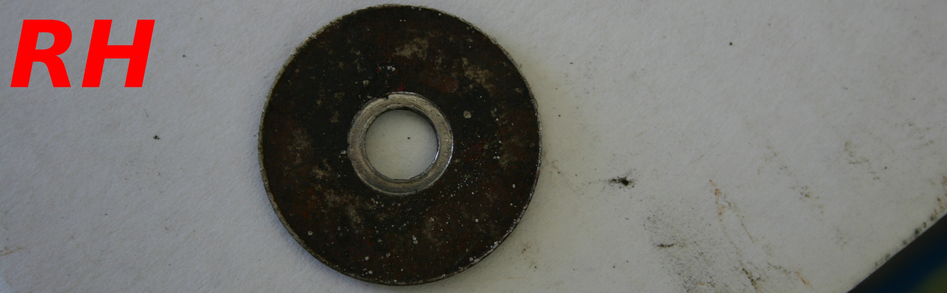
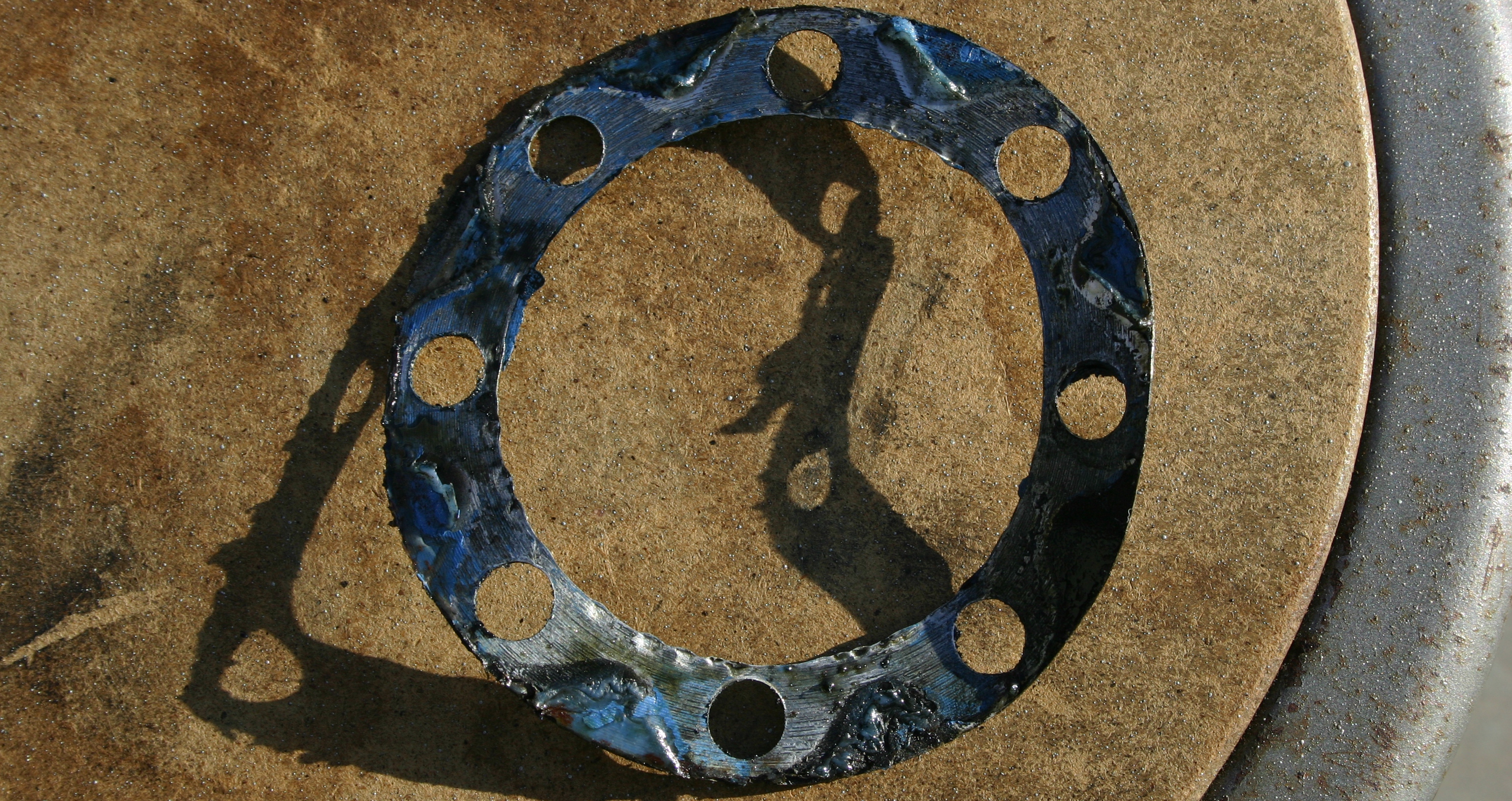
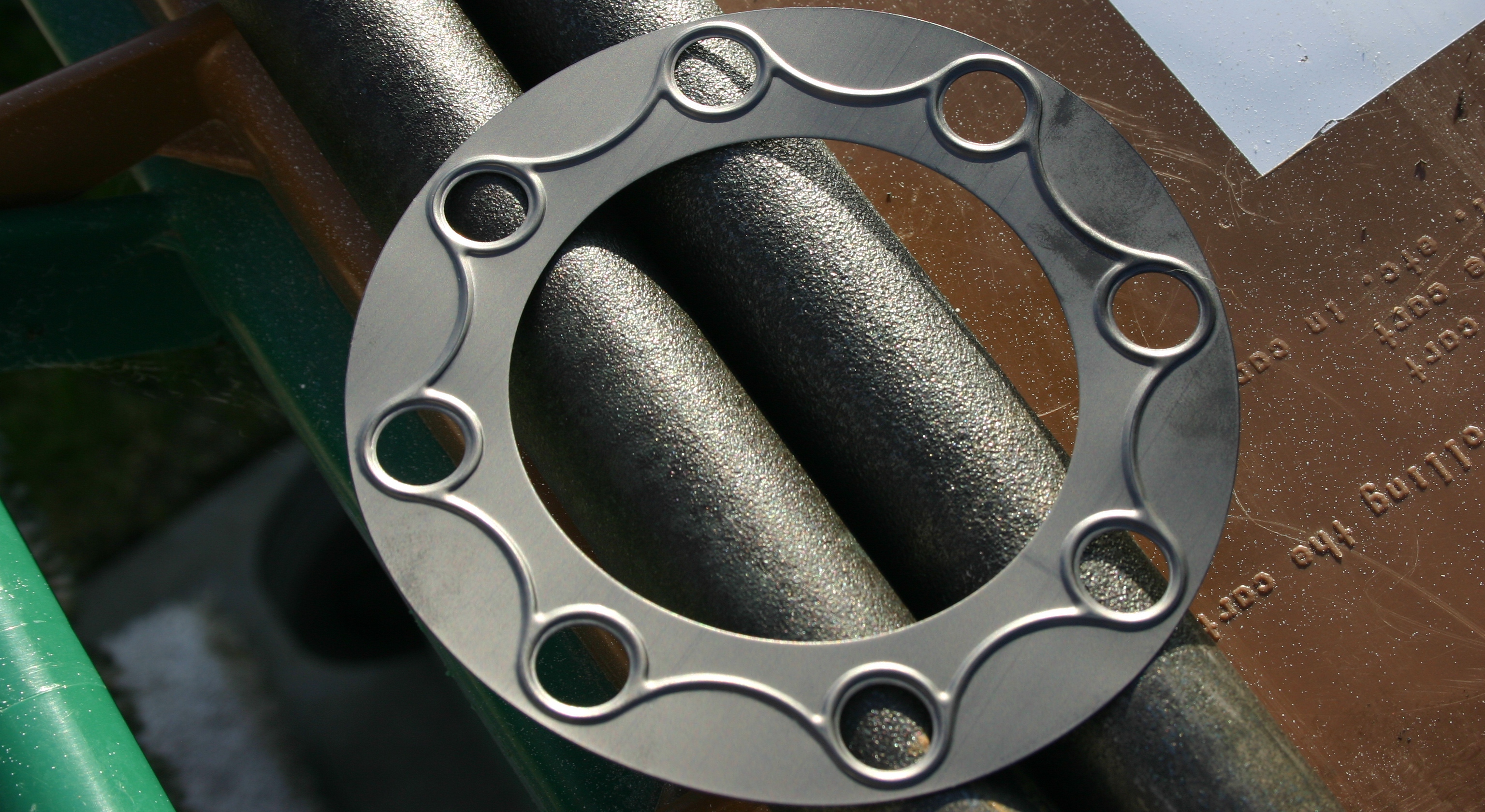
And the large washer; it was bent, just like on the LH side. I smashed it back in to shape.

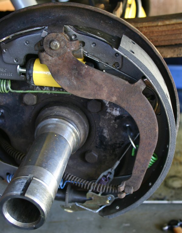
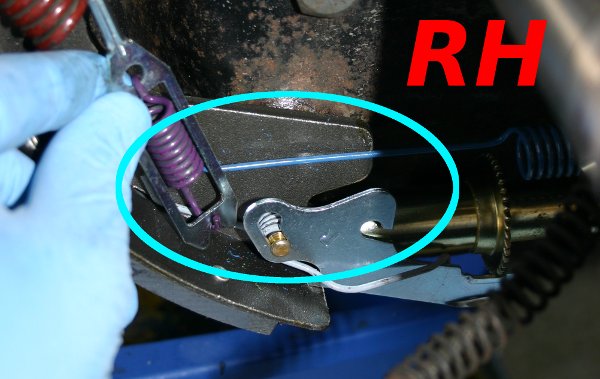
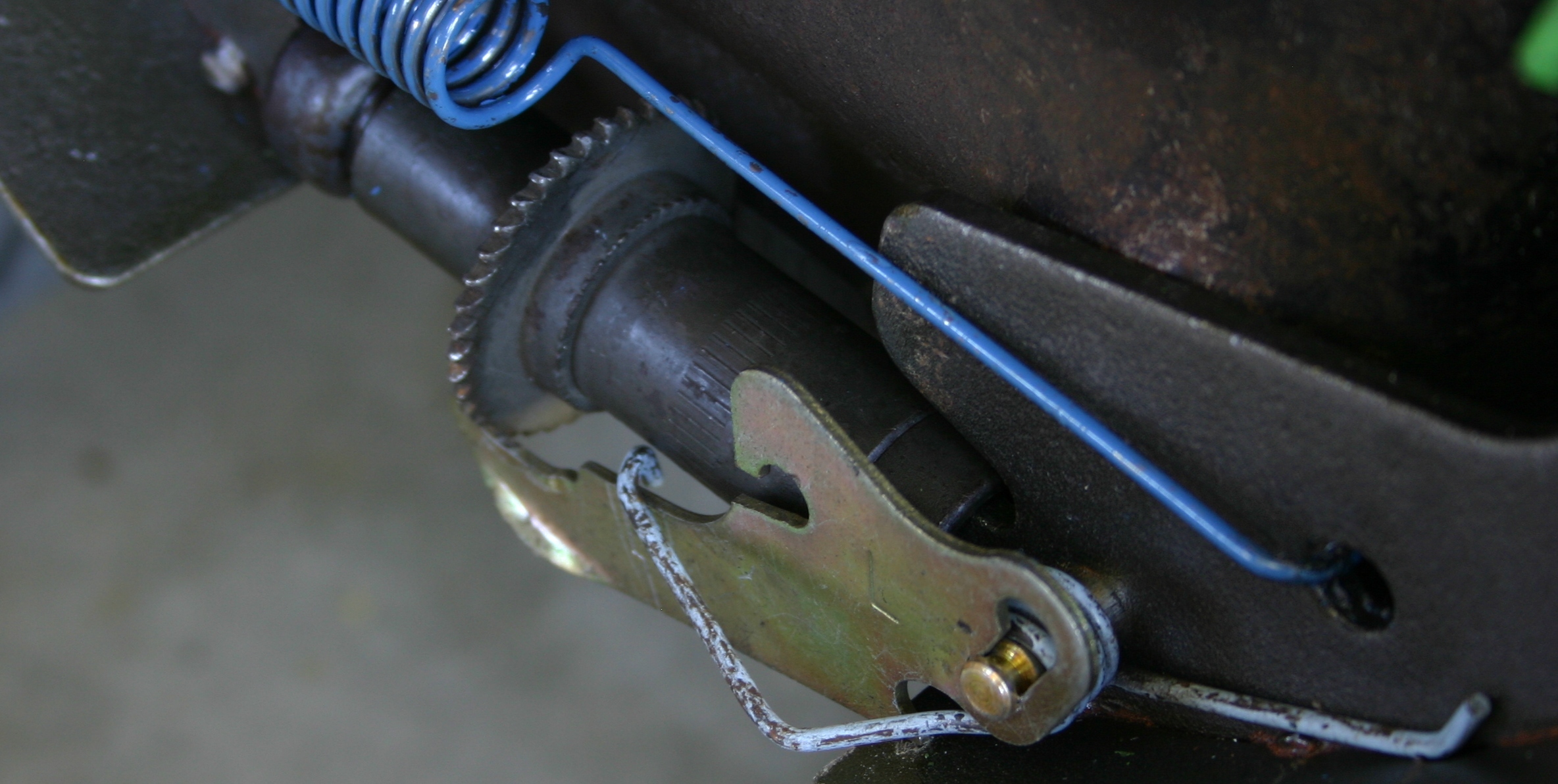
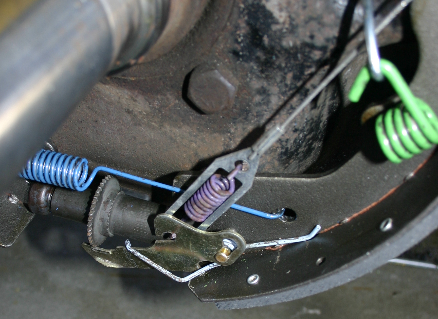
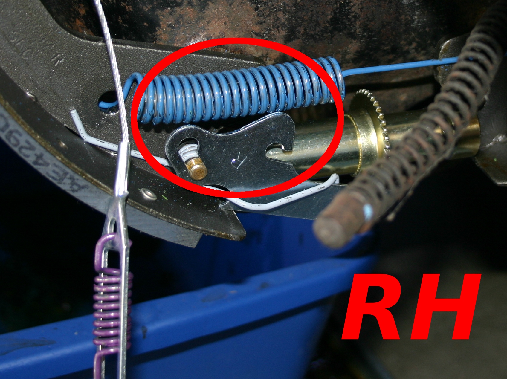
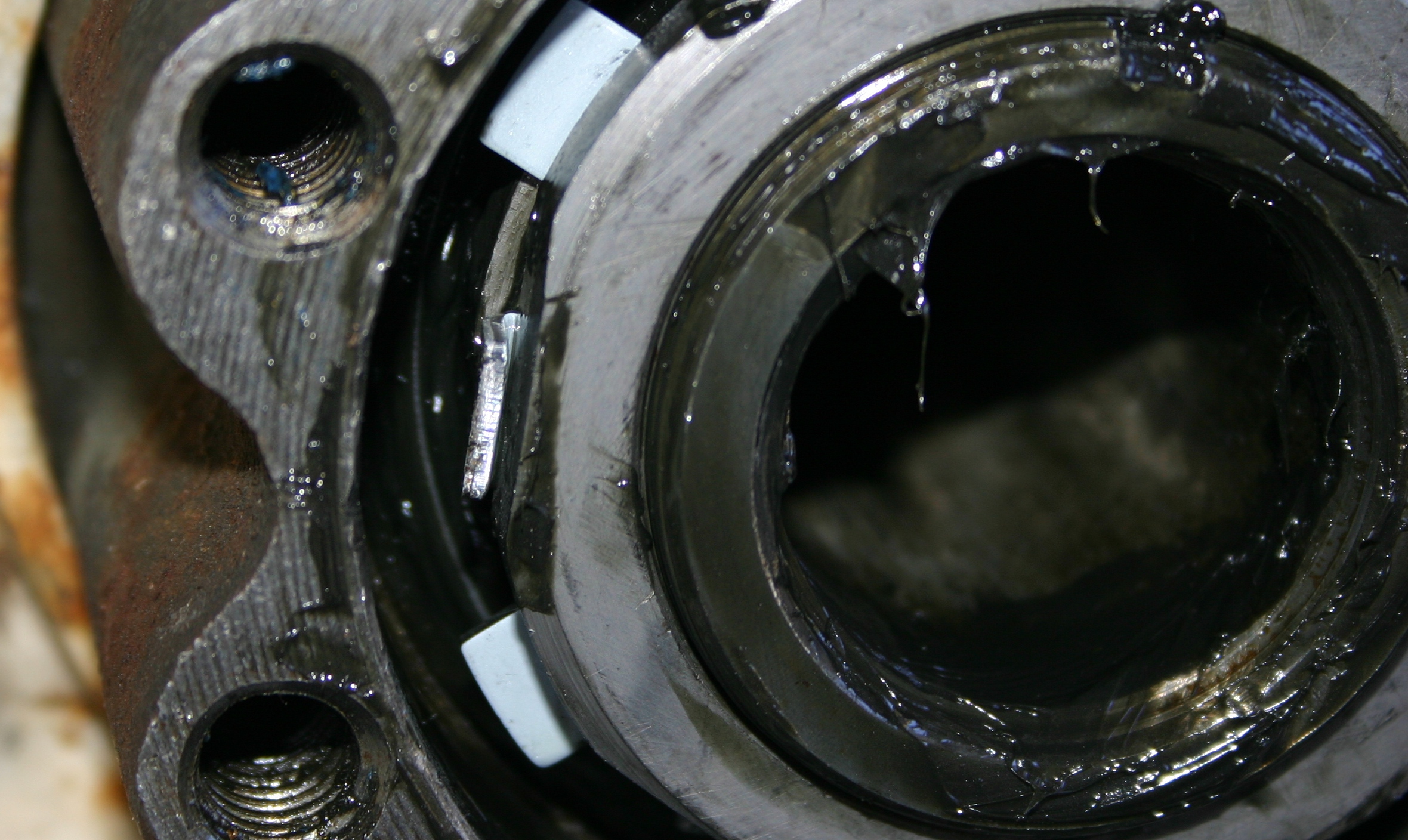
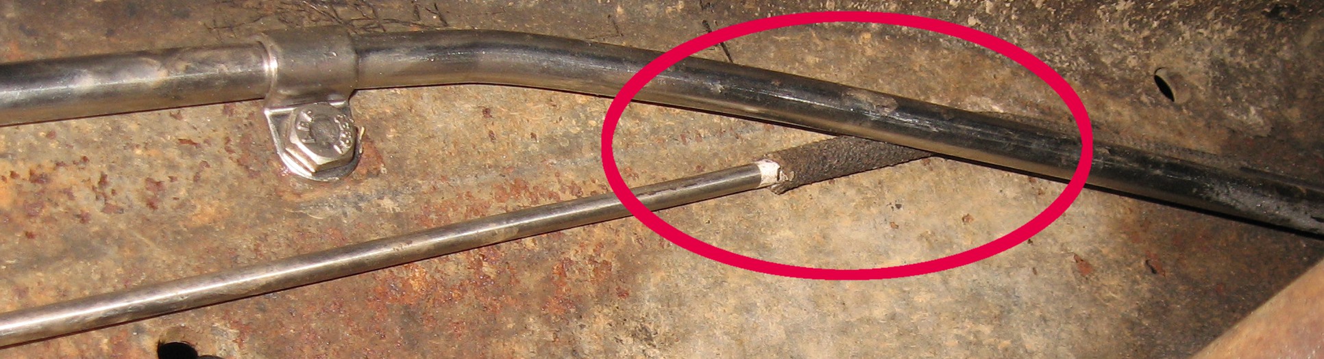
After looking at those individual parts, I went to test fit the cable to the adjusting lever, and realized that I'd installed the lower retracting spring backwards (in the red circle)!

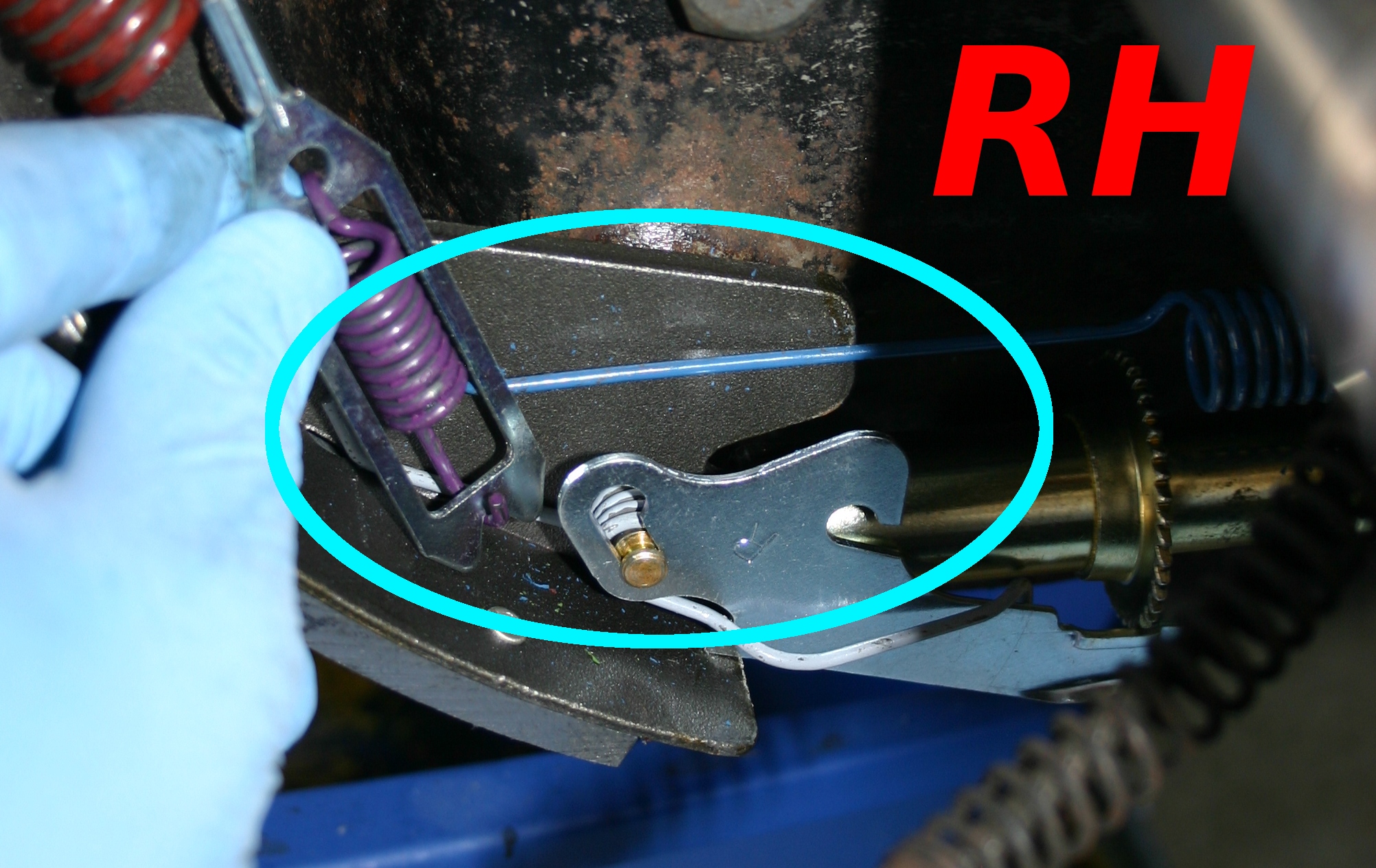
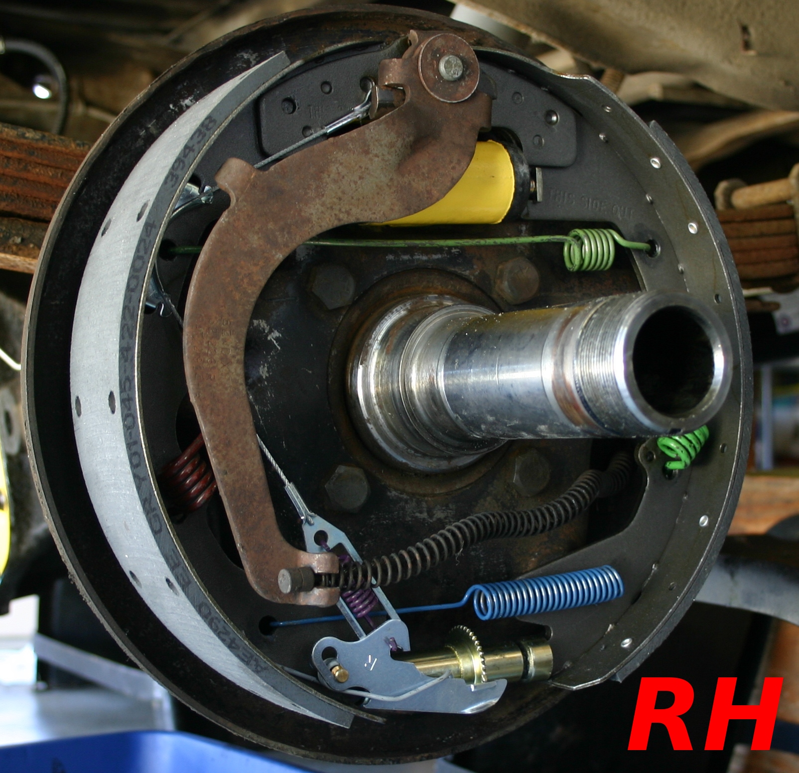
I reversed the lower retracting spring and then had plenty of room (light blue circle).
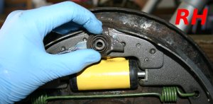
Here's the documented build-up of the RH-side parking brake lever assembly. First, I inserted the odd 2028 spacer in to the cable anchor fitting (2A178) as shown, holding it up to the backing plate (left). Next, the "chicken head bracket," 2A142, fit on the 2028 spacer, with its "beak" facing the front of the truck (right).
The 2A601 spring's held on next, centered on the 2028 spacer (left), then the parking brake lever itself is layered on (right).
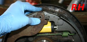
I set the large washer on top of the parking brake lever, doing my best to keep all the parts centered.
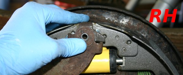
Then I shoved the parking brake assembly bolt through the whole mess, carefully tapping it through the assembly, allowing it to mate with the splines on the odd 2028 spacer. Of course the whole thing kept trying to come unglued so it took a couple of tries!
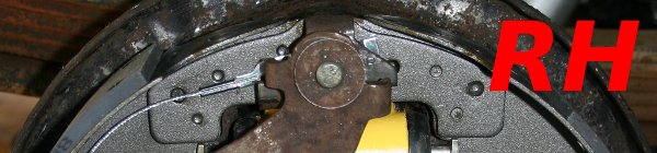
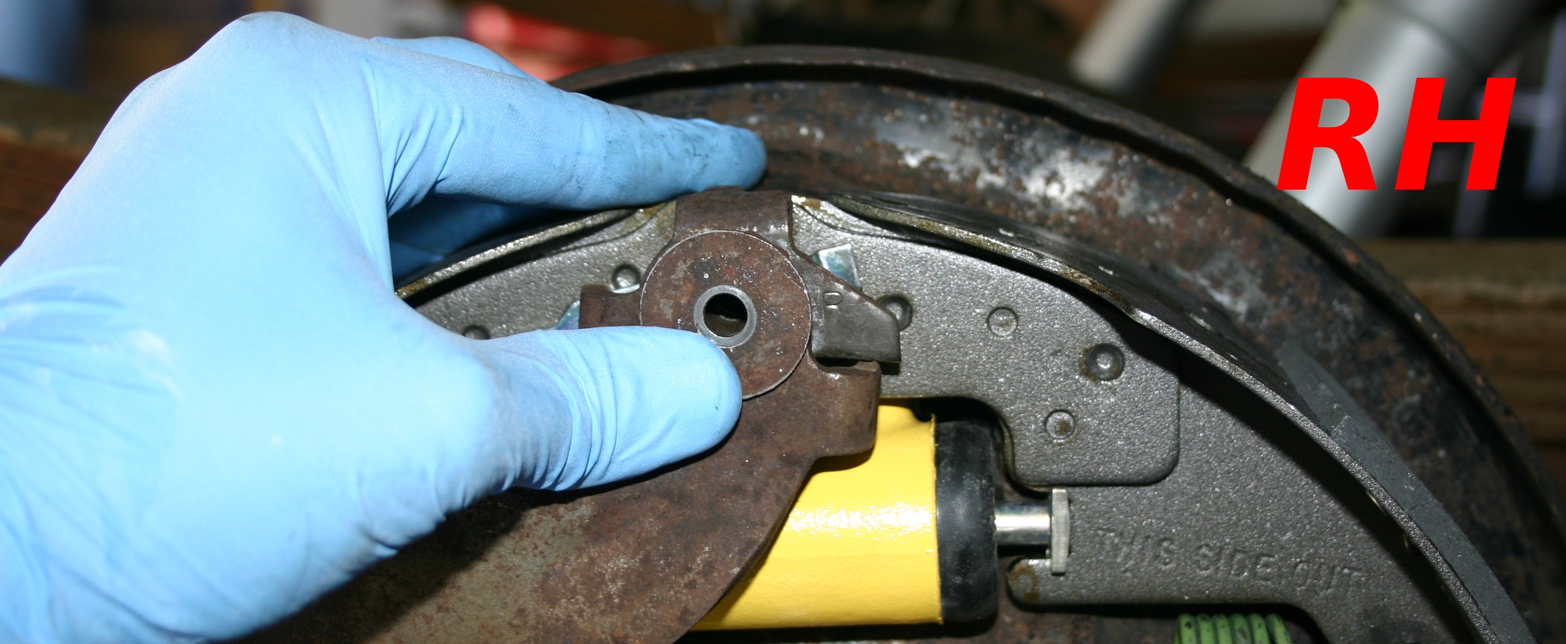
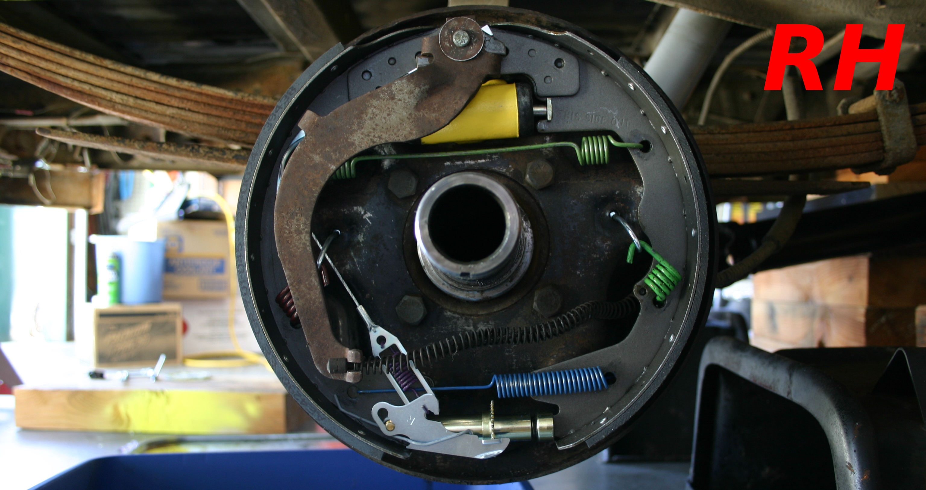
Here's the RH side, basically ready to begin the initial drum fitting process.


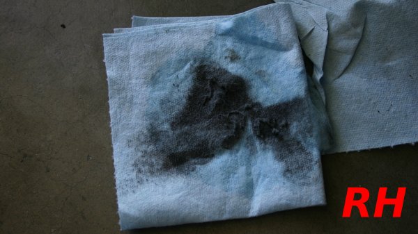
Following Fordman's advice, I put some brake cleaner on a clean towel and wiped off the brake shoes. You can see what came off! I think it was just dust from the shoes though, and not grease or oil, since there seemed to be no end to it.
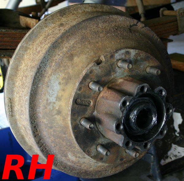
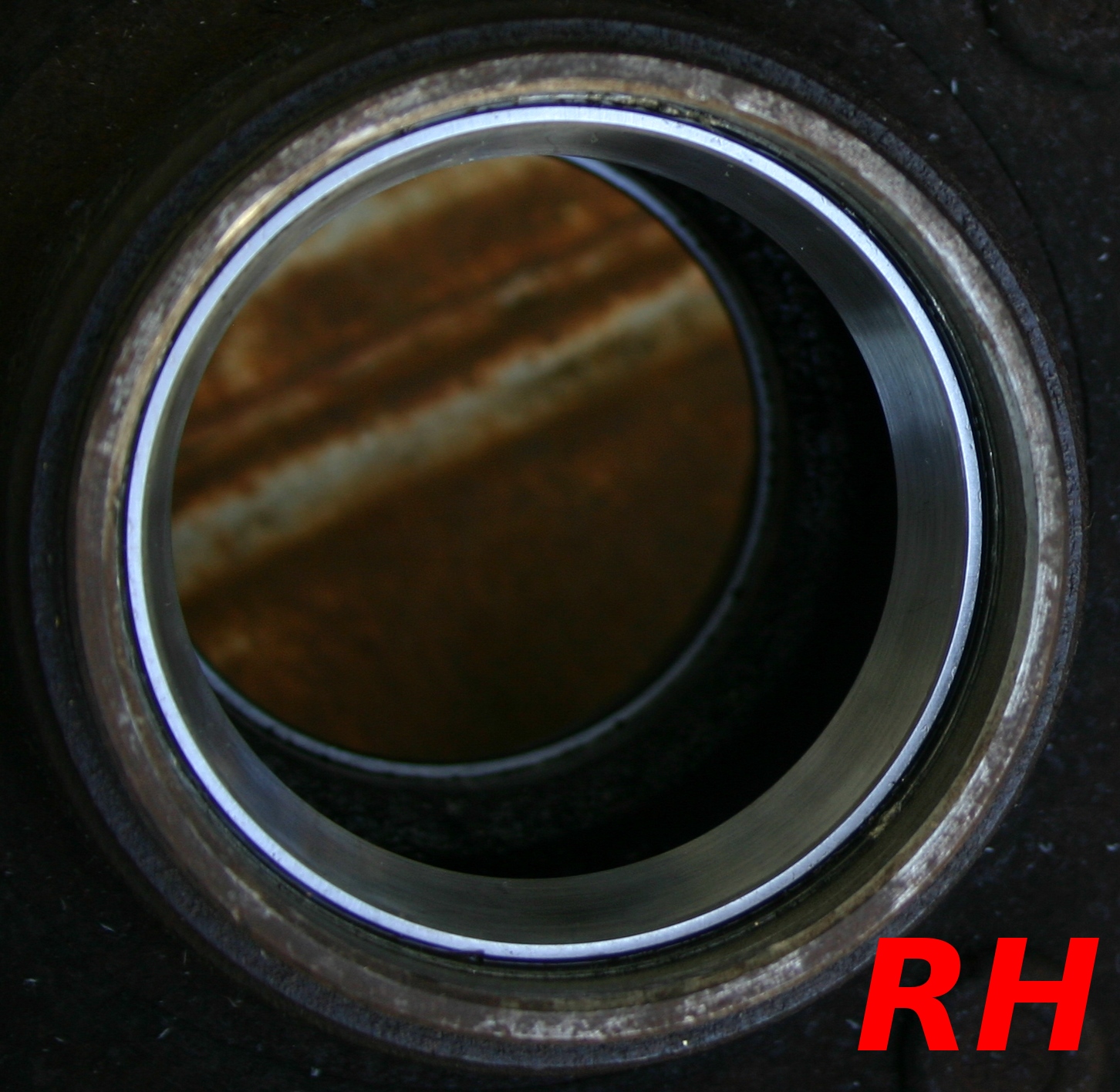
Here's the drum I selected for installation on the RH side. During storage, I kept spraying WD-40 on the races to keep them from corroding. So thankfully they remained in perfect condition (left)! I packed the inner wheel bearing with high temperature grease and set it in place (right).


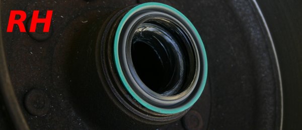
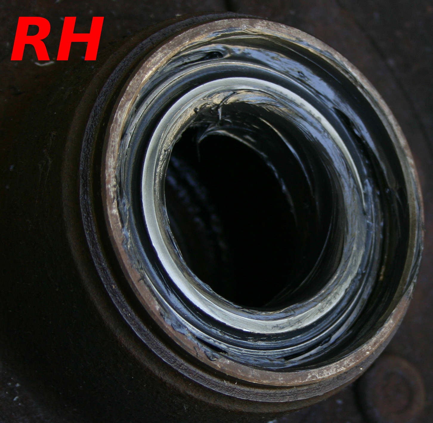
Here's the new seal resting over the inner bearing, ready to tap in to place. Thankfully it went in willingly with no special tools!
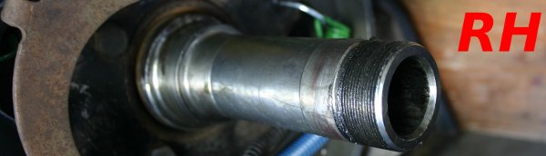
I then put an even, thin coat of grease over the spindle. It's probably not easy to see in this photo, yet it's there.
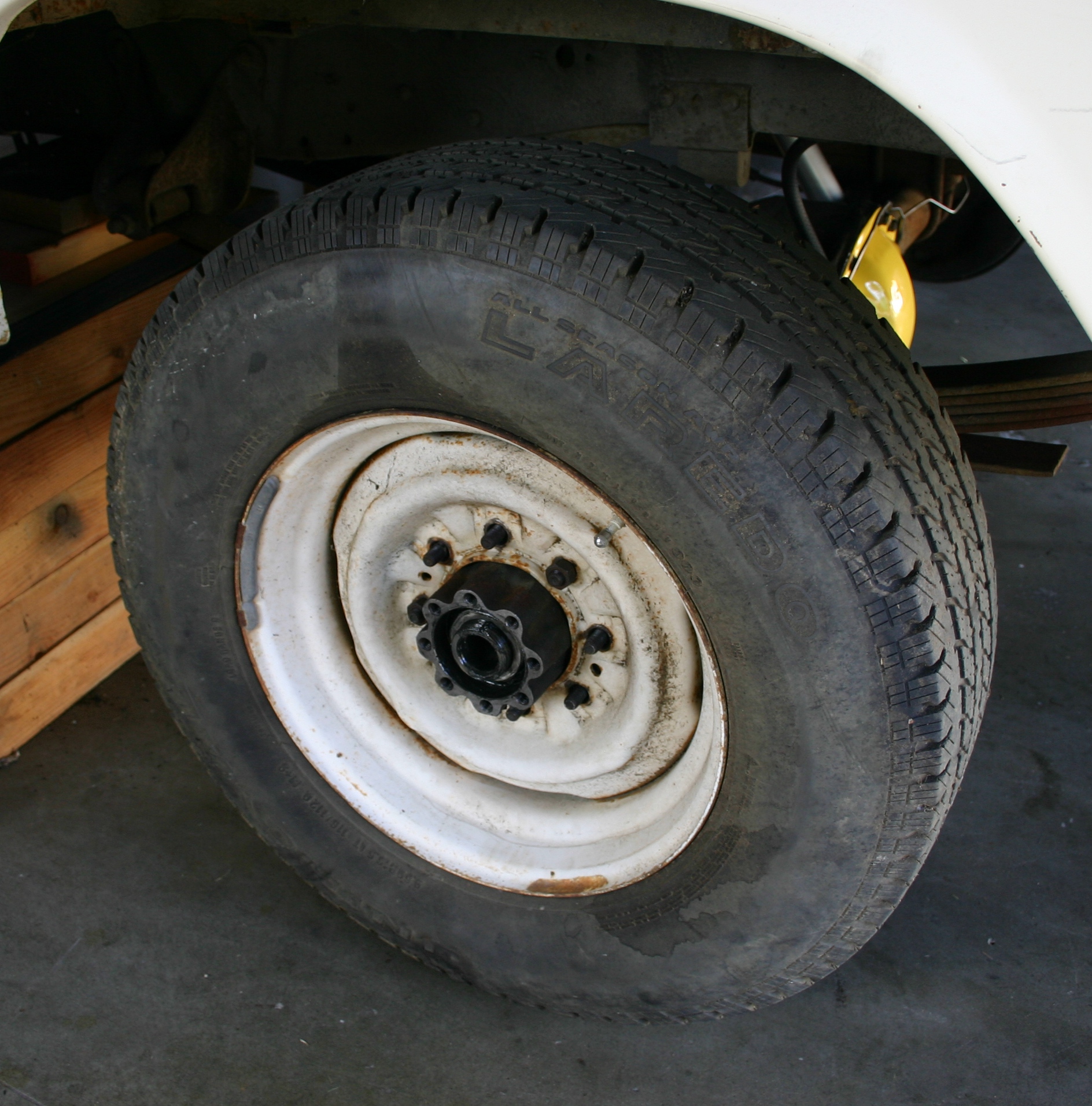
I used brake cleaner to make the inside of the drum immaculate, made sure the shoes were adjusted to their minimum travel, and arduously placed the drum in position--it went on with no interference whatsoever! So I pulled it off and increased the brake shoe travel several times before finding the sweet spot, where it was possible to slide on but definitely not a free fit.
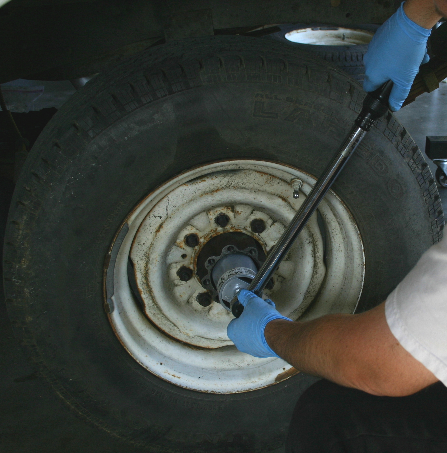
I put this torque wrench together with the big KD socket and threaded the nut over the outer bearing, taking care to keep the drum turning during this process, presumably to prevent an unwanted bind. I was following
GSequoia's great instructions! Yet I didn't put any kind of torque on the nut yet (more on this in the question section).
Following the same process, I got the LH drum tentatively installed, yet I didn't torque down the nut over its outer bearing yet either.
 This Afternoon's Questions:
Beginning today, I'm putting a unique ID in front of each question. These IDs can be referenced later--this system should help to keep track of any questions that are revisited later on.
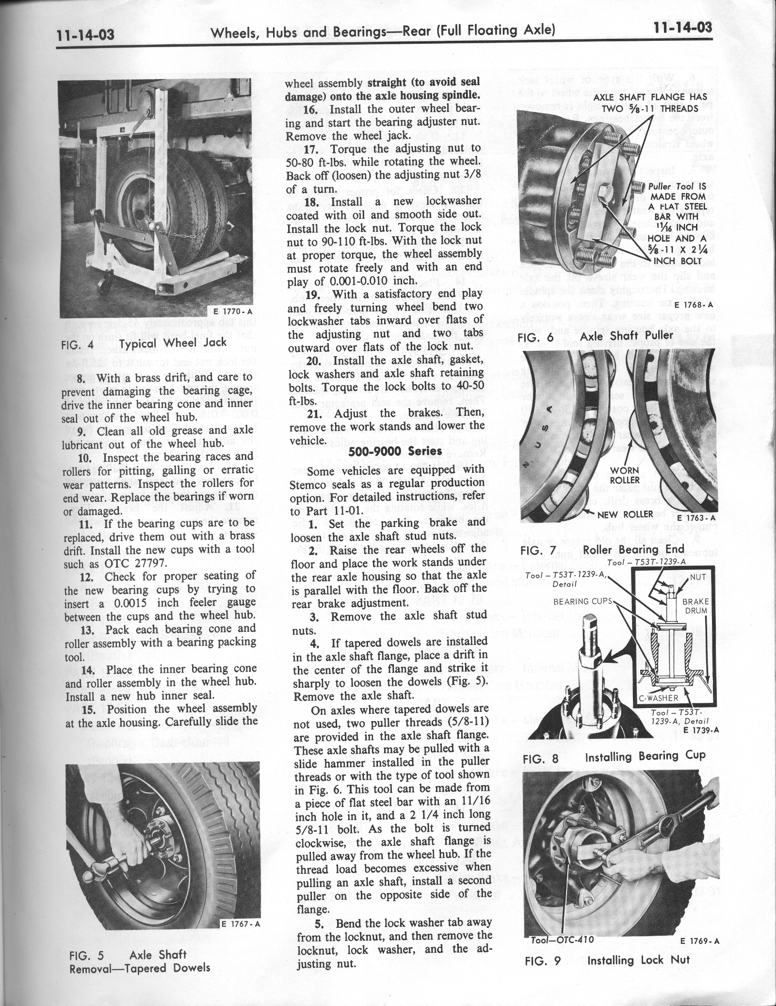
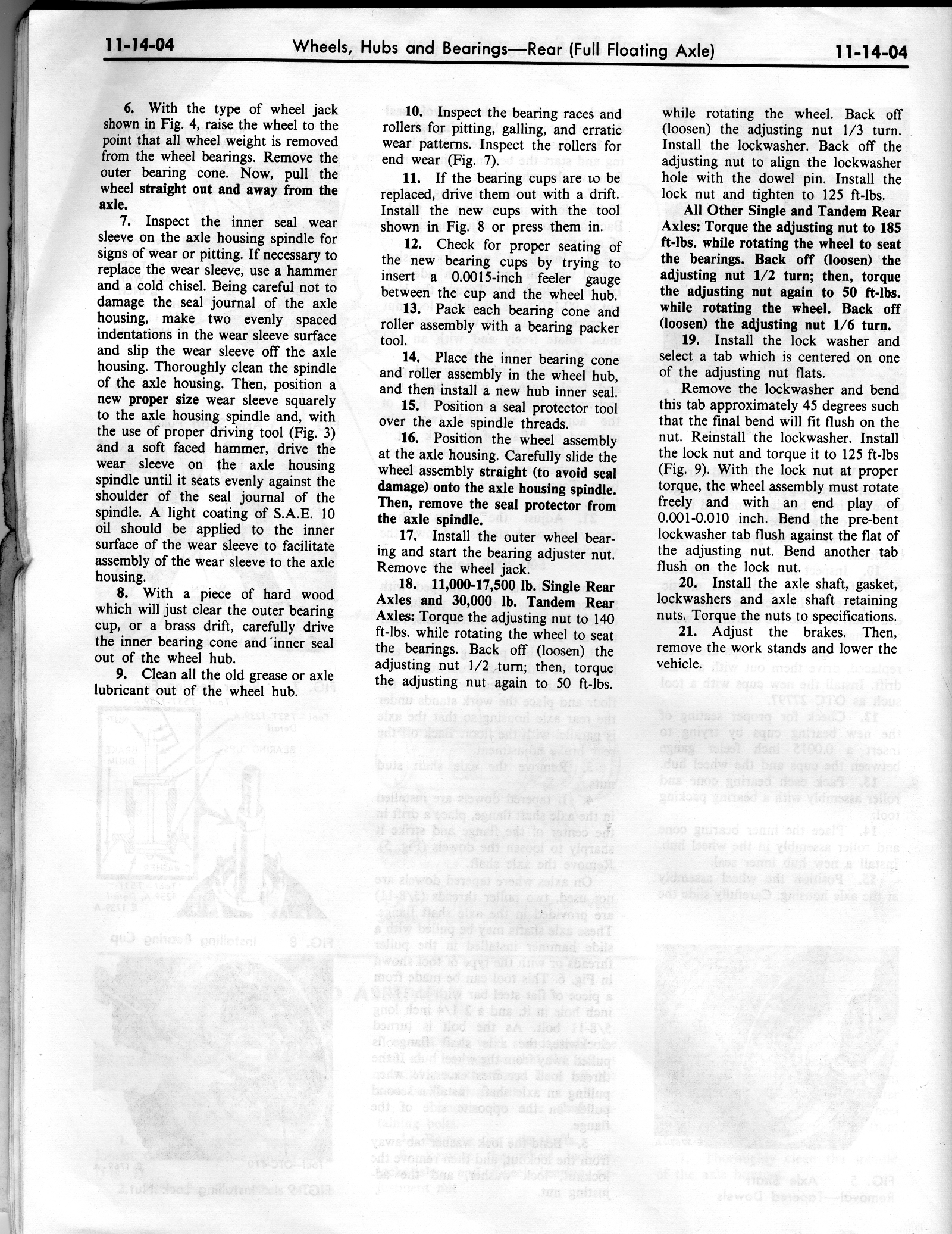
- ID 1: I read in GSequoia's great instructions that I should install a wheel on the hub, then while turning the wheel, torque the inner nut (that presses up against the outer bearing) to 50-80 ft/lbs before backing it off 1/3 of a turn. 50-80 ft/lbs intuitively seems like a lot of force to be putting on the side of that bearing, and I wasn't able to confirm this torque spec in the 1970 and 1972 Ford Truck Shop Manuals. Shall I really get the big nut that tight before backing it off 3/8 of a turn?
- ID 2: In the next step in GSequoia's great article, I read that with the inner nut in place, the outer nut should be torqued to 90-110 ft/lbs. Again, intuition tells me that this is pretty tight, and I'm not able to confirm that spec in the Ford manuals. Is this truly the best action to take?
Thanks very much for wading through my long update, and for all the superb guidance!
Robroy


