
I should have taken pictures when I was doing it, but didnt. I have to take the dash off today because I want to change my Tach bulb to Green, so I will snap some shots when it is apart and post them here and you can see what I did.
I contemplated taking the Auto Meters apart and mounting the innards, but did not feel good about taking apart $250 worth of new gauges and possibly screwing them up, so came up with the method I used and it worked great! I bought Auto Meter Old Tyme gauges (black) and they look good with the stock F600 speedo.
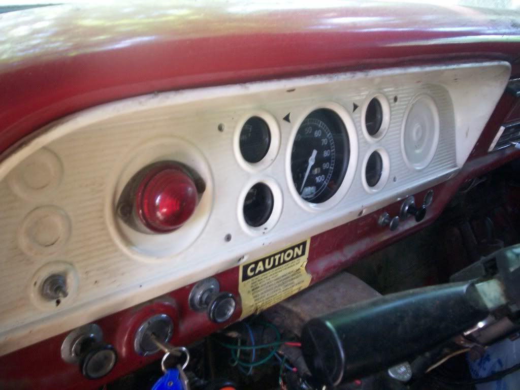
This is the dash (not truck) I originally started with:
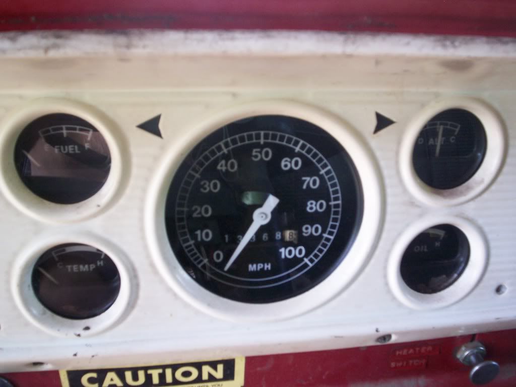
A while ago, I painted the dash and mounted an Auto Meter Old Tyme tach. I also moved my gas tank selector switch to the upper left spot on the dash, and my emergency flasher switch to the lower left of the dash. I put a second cigarette lighter in the location where the emergency flasher was originally. This way I have multiple power sockets in the truck. Here is a picture of it painted with the Tach in it (gas selector and emergency not shown):
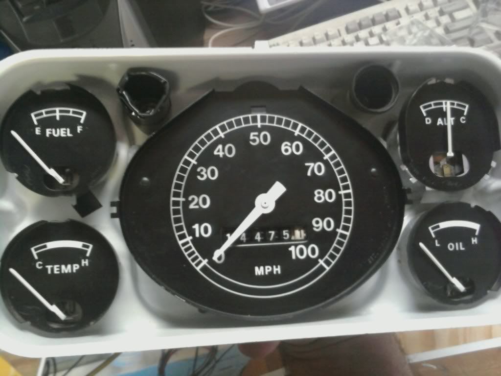
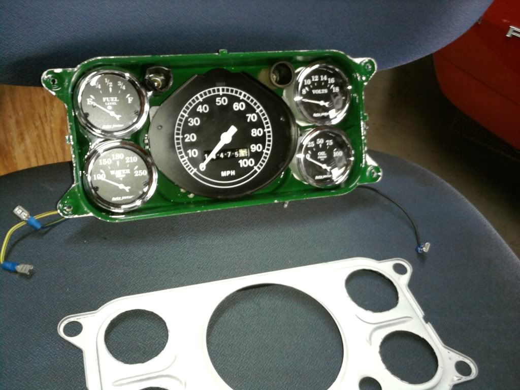
And a picture of how the stock gauges sat inside the dash when apart:
I will go and work on it this afternoon taking it apart and will put some pictures of my modifications up in this thread later today.
Ok, I had typed a long post and just about finished when my browser froze... so here I go again.
Before I show how I did my gauge panel, I will explain some modifications I previously did to my wiring so it is easier to understand how I ended up wiring my gauges. Previously when I was installing my stereo and additional components, I wired in 4 relays under my dash from the battery so that I would not have to over-tax my ignition wiring. With these 4 relays, I initially used three of them leaving one free for future additions (like these gauges). The original 3 relays were used to power my stereo, my second cigarette lighter/power socket in my dash, and a 3rd hidden power socket in my glove box which powers my iPod.
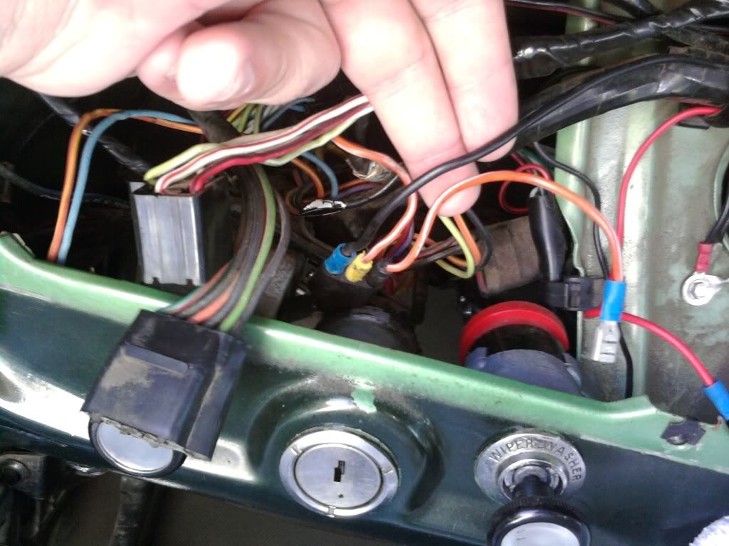
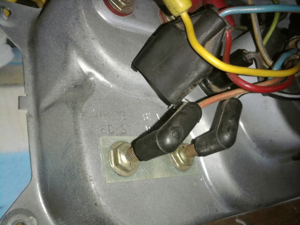
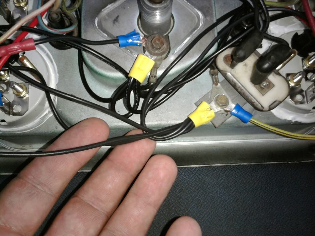
These relays are turned on/off from one of the 3 stock ignition slots. The other 2 ignition slots are used by my windshield wipers (just like stock), and my Tach. Here is a picture of my ignition wiring. The black wire is the on/off for my relays, the short wire with the female plug attaches to my Tach,and the other orange wire going into the back handles the windshield wipers:
Here is a picture of the 4 relays mounted under the dash above the steering column:
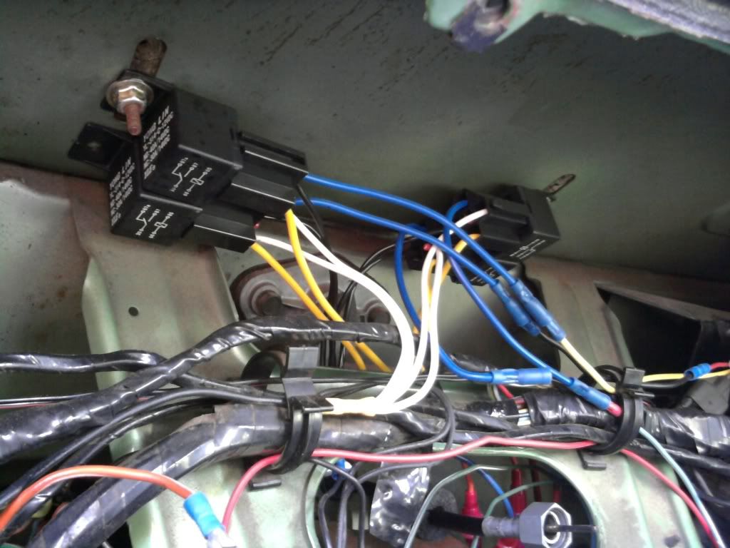
And here is the previously unused 4th relay plug which now powers my 4 new gauges:
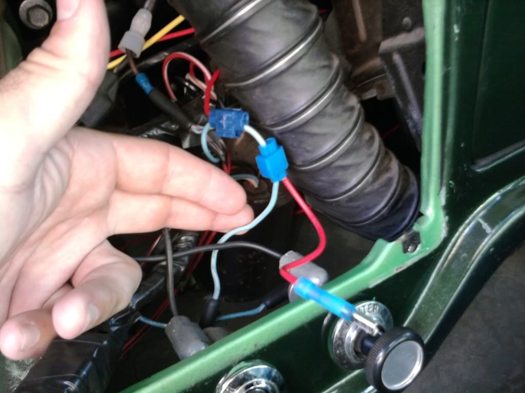
To power my clock that I installed, I tapped into the stock cigarette lighter which is always hot. I also tapped into this wire for my stereo memory (radio stations/clock). Both the clock and the radio memory are low draws and the lighter wire more than handles this:
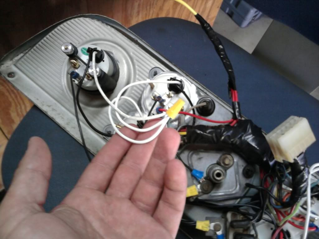
Now that the under dash wiring is explained, I will get into the gauge cluster. Here are a couple of before photos from the back prior to cutting out the holes for the new gauges:
Now here are after shots from each side once the holes had been cut, gauges had been mounted, and gaps had been sealed:
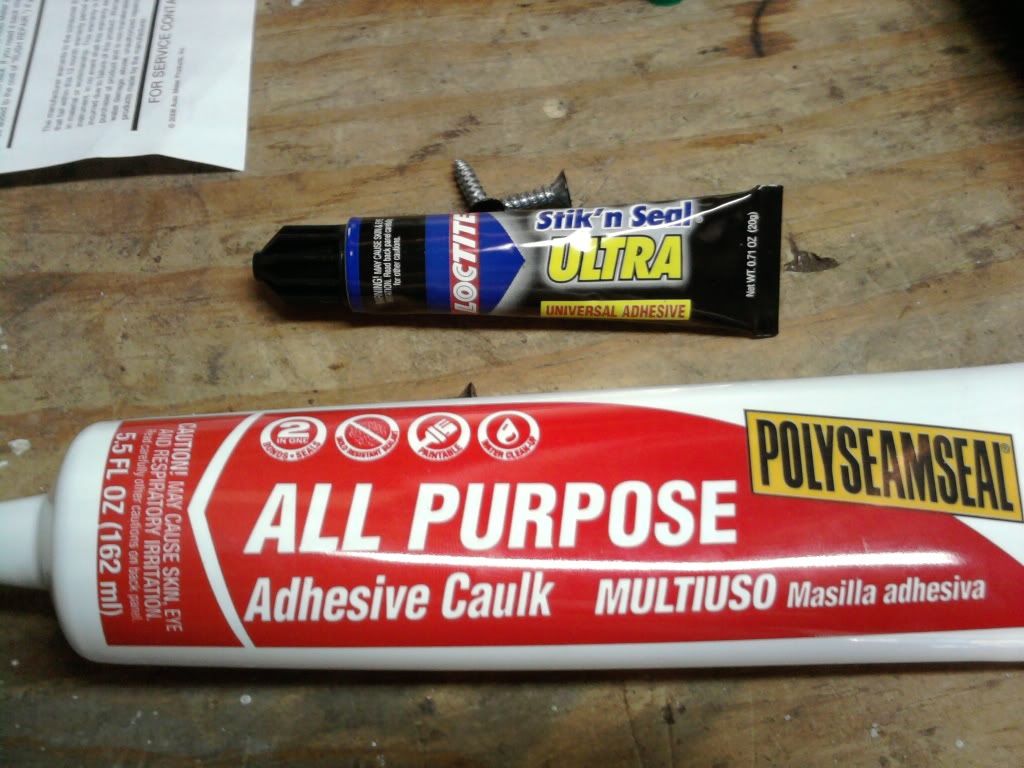
When I first cut the holes and put the gauges in, they were tight enough to basically hold them in place, but I used a few drops of Loctite Stik n Seal Ultra on each gauge to secure them in place (5 minute setting time). Once I had them positioned how I wanted them and set in place, I then sealed around each gauge with another Loctite product that is a rubberized adheasive caulking. I used this so that in the event that I ever need to remove a gauge for whatever reason, I can just cut the rubber seal without damaging the gauge or housing. I also liked that it dries white as the inside of my housing was originally white. Here are the 2 products I used:
I decided to use green lights in my Auto Meter gauges so I wanted to tint the light green for my stock speedo as well. I painted the inside of my housing with a hunter green so that it gives the light a green tint. i left the inside of the face white so it is still highly reflective with a green tint. I cant get it to photo well, but it is a nice green tint that goes right along with the green lighting of the new gauges.
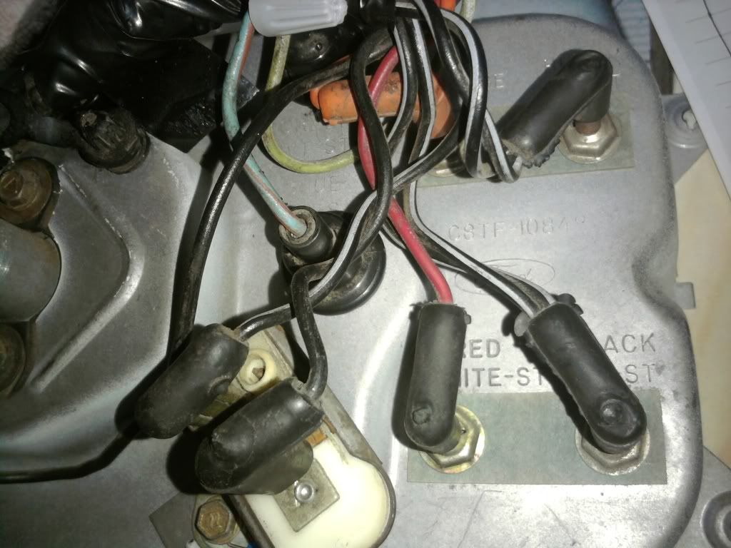
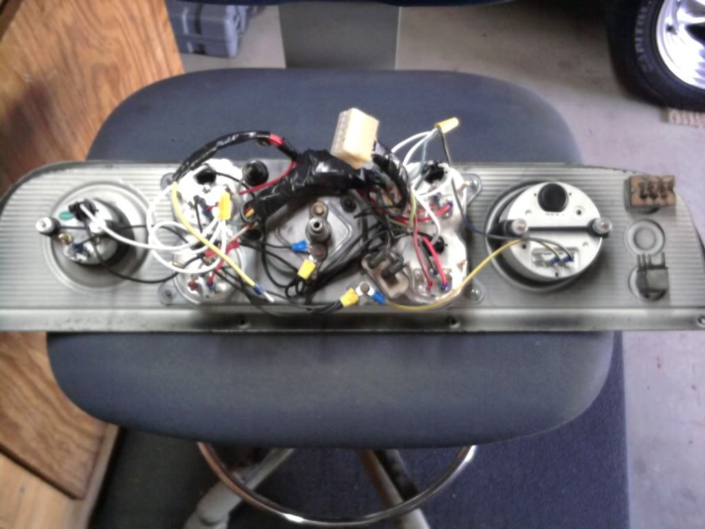
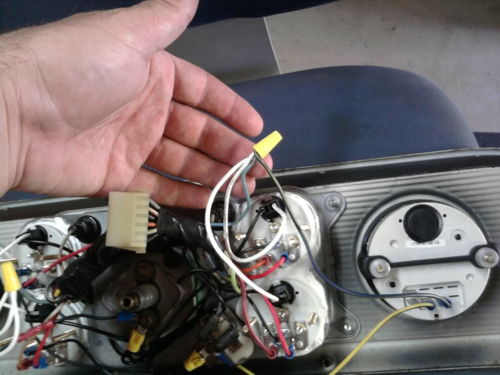
Now for the wiring of the gauge cluster... Here is an overall view of the back. At first glance it looks like a bunch of spagetti, but it really is a simple layout and not as bad as it looks. The large black taped wad is the unused wires of the stock harness. I used the same sending wires for the fuel, temp, and oil (I replaced the stock sending units for Oil and Temp with the ones supplied by AutoMeter). I also used the same lighting wiring (blinkers, brights, gauge lighting), as well as the main ground (solid black) which grounds the housing. I did not use the old gauge grounding (black with white stripe) and those are taped up in that bundle along with the old Alt wires. The only reason the regulator is on the back still is to fill the holes where it mounts. I re-wired it with the stock wires in case it needed to complete some unknown circut in the stock wiring, but it serves no purpose with the new gauges.
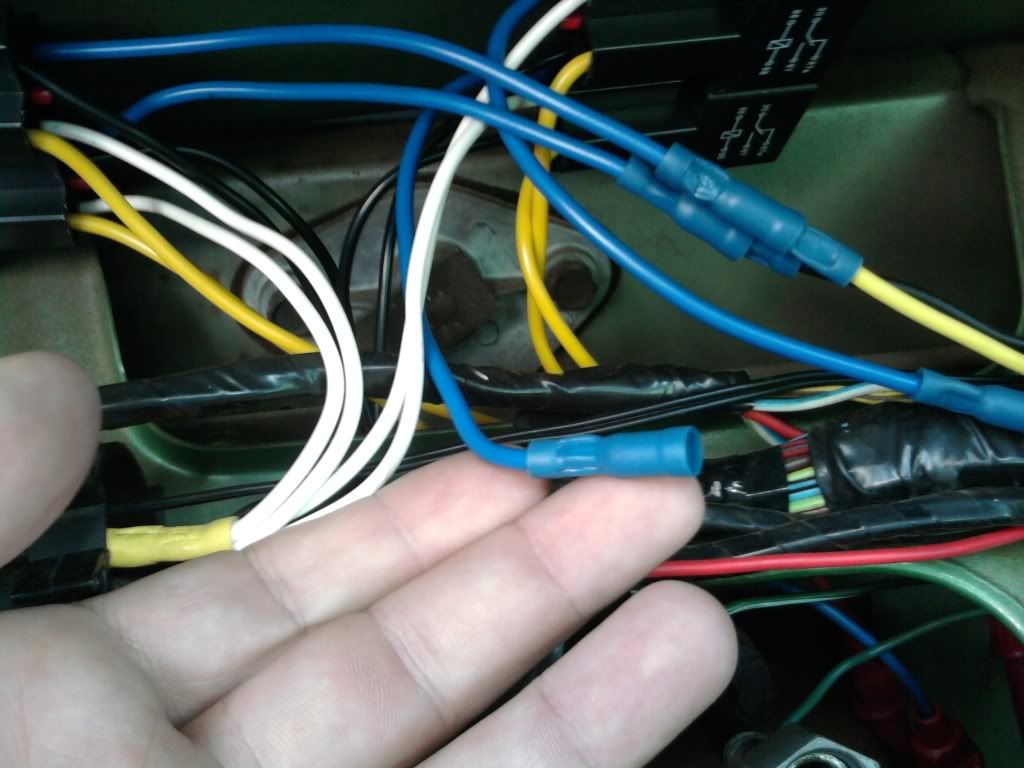
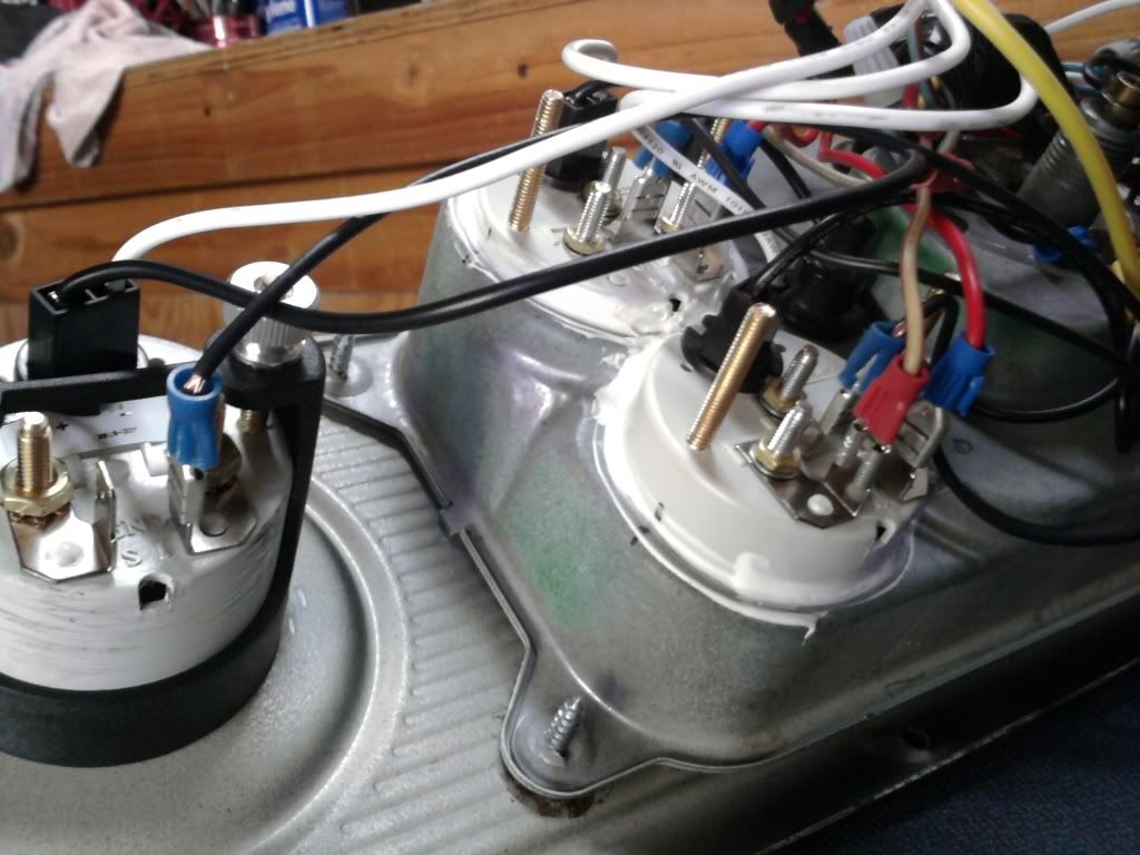
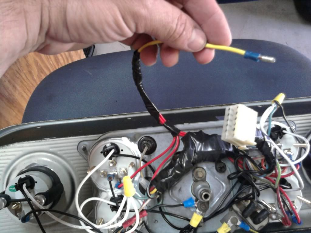
Now for the other wiring.. All of the power wires for the 4 new gauges were wired together and attached to a plug which attaches to the previously shown relay:
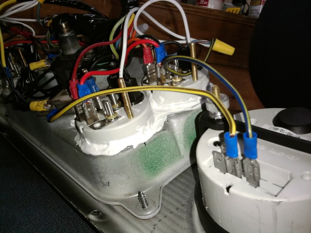
All of the grounds (6 lighting grounds for the 4 gauges plus clock and tach, and 6 power grounds for same) are all attached to the two stock grounding locations used by the previous gauges:
The positive wires for the gauge lighting were attached into the stock lighting wiring. The 3 left gauges were attached to the left side wire, and the 3 right were attached to the right side wire:
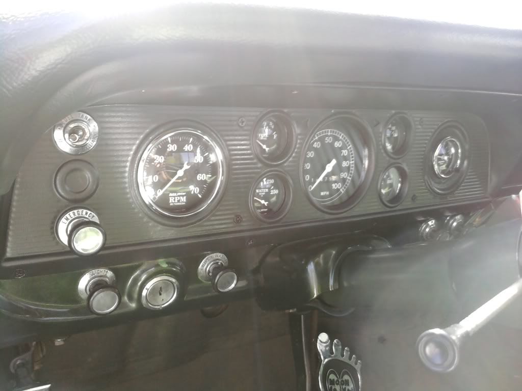
And as for the wiring, that pretty much was it. Every gauge worked perfect the first time I hooked it up. My only intial concern with this method of mounting them was the 4 gauges being under double glass (the gauge housing, and the glass for the F600 dash). Once installed though, there were no issues. All 4 gauges are easily viewed during both day and night conditions. You dont even notice that they are under 2 pieces of glass.
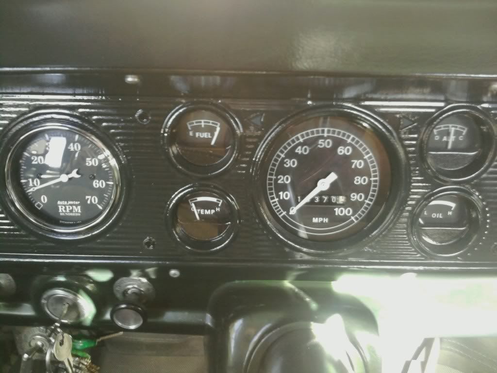
Here are some pictures of everything installed and working:
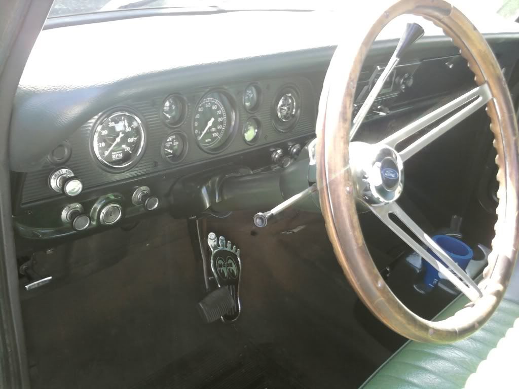
Thats pretty much it!! Hopefully I made sense and your are not disgusted by my "do-it-myself" cutting, mounting, and wiring. I definately am no RobRoy (your stuff is awesome!!) but I get by. If anyone has any other questions, fire away. I learned as I went and I think it came out pretty well.


